Next I would like to build some sort of varying load circuit to test the load regulation of each of these devices. If anyone has a recommendation, please let me know. Battery biased mosfet as the load, driven by a sine signal generator perhaps?
[/B]
Drawing about 50% peak to peak of available set current on shunt's CCS, will be fare I guess.
Bump, bump, keeping the thread alive.
Jam,
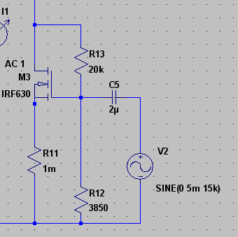
OK, so I'm thinking this will be the active load that I'll use to test load regulation (how stable the output voltage remains when a load draws a varying current). An irf630 mosfet biased via a voltage divider and fed through a coupling cap from a sine generator.
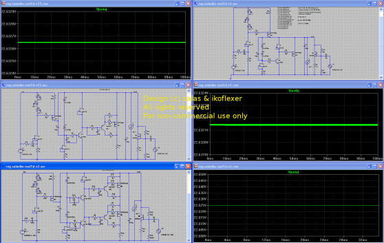
Simulating this sort of thing shows some interesting results for v1, v1.5, and v2.
In the simulation I set the bias so that the mosfet draws about 85mA DC. The sine generator adds a wiggly AC component of about 5mA at a frequency of 15kHz, towards the top range of audio frequency.
Click on the image to see it large.
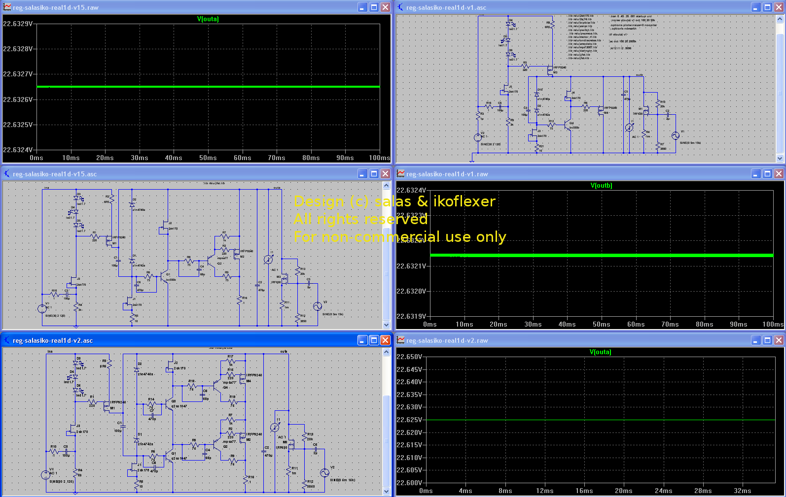
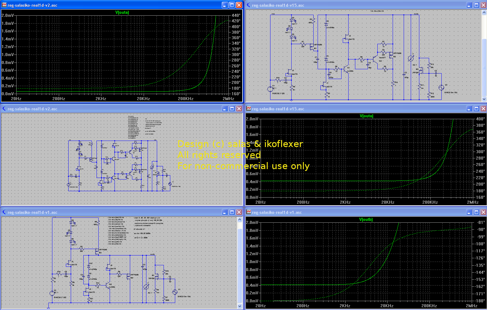
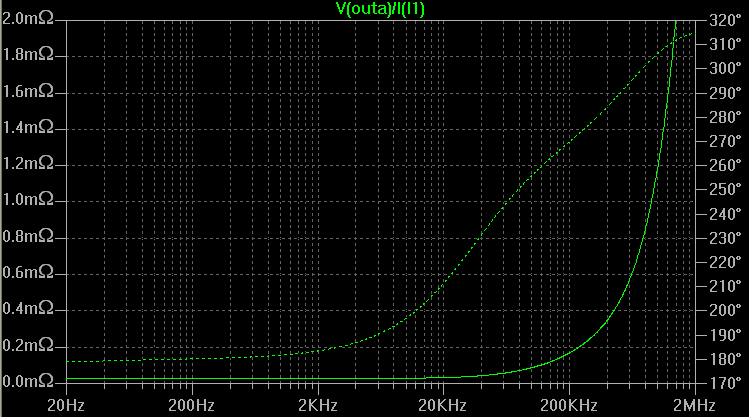
Edit: for fun, the output impedance of all three versions, tete-a-tete. Read the result in milliohms, not millivolts; I just didn't divide by the current, the numbers and curves are exactly the same. This shows that v1 is just excellent. v1.5 offers the same excellent performance on a wider bandwidth. v2 offers even lower output impedance on a wide bandwith.

I welcome comments/suggestions.
Jam,
OK, so I'm thinking this will be the active load that I'll use to test load regulation (how stable the output voltage remains when a load draws a varying current). An irf630 mosfet biased via a voltage divider and fed through a coupling cap from a sine generator.
Simulating this sort of thing shows some interesting results for v1, v1.5, and v2.
In the simulation I set the bias so that the mosfet draws about 85mA DC. The sine generator adds a wiggly AC component of about 5mA at a frequency of 15kHz, towards the top range of audio frequency.
Click on the image to see it large.
Edit: for fun, the output impedance of all three versions, tete-a-tete. Read the result in milliohms, not millivolts; I just didn't divide by the current, the numbers and curves are exactly the same. This shows that v1 is just excellent. v1.5 offers the same excellent performance on a wider bandwidth. v2 offers even lower output impedance on a wide bandwith.
I welcome comments/suggestions.
In practice I found the LED biased mosfet to be more stable even for v1. I would recommend to allow for that on the current pcb, just in case of oscillation.
I think numero 2 on the list should be that someone actually use the pcb to build the thing and report that the pcb is actually working as advertised. I don't see why not, but it's always better to have real confirmation.
Then, we should probably come up with a BOM. and then people can organize a PCB group buy. I suck at organizing things so, someone else has got to do it.
All this pertains to v1. As far as v1.5 and v2 goes, I'm going to put some more work into them, tests, etc., then pcb.... and we'll go where no discrete shunt regulator has gone before.
Ok, ok, I'm just kiddin'
As you know I kept on recommending the LEDs version to p2p DIYers in many cases before, bcs even if little less capable for ripple rejection (not really that different in practice), I noticed that it was more non careful proof. Especially when probing. Yes I think its good to be there.
leds
Okay, Salas, Ikoflexor, Leds, eh. As per your Circuit for the RIAA in Nov last year? This is just adding the option of using 3 leds in place of Q2, R2? That's straightforward - just add extra donuts for the 3 leds replacement for the R2, and then jumper the Q2 donuts - perhaps something a little more refined? Do you want to keep the C1 reduce any noise that 3 leds in series generate? And it's resistor, Rc?I'm "nutting out" a rough layout for a +/- version with simple Cmultipliers on the inputs for extra ripple reduction and lower Z - the Cmx is a very useful thing! [The G,D,S pins layouts suit IRP610 (9610), 2sj380, 2sk2391, etc.]
Okay, Salas, Ikoflexor, Leds, eh. As per your Circuit for the RIAA in Nov last year? This is just adding the option of using 3 leds in place of Q2, R2? That's straightforward - just add extra donuts for the 3 leds replacement for the R2, and then jumper the Q2 donuts - perhaps something a little more refined? Do you want to keep the C1 reduce any noise that 3 leds in series generate? And it's resistor, Rc?I'm "nutting out" a rough layout for a +/- version with simple Cmultipliers on the inputs for extra ripple reduction and lower Z - the Cmx is a very useful thing! [The G,D,S pins layouts suit IRP610 (9610), 2sj380, 2sk2391, etc.]
There is not a change really in simplistic V1. Its straightforward and can be made either with a Vbe or LED Vref for its main CCS. The PCB is already developed by James, and any layout additions will be posted here. Due to its low parts count it has already been made in P2P by many members since late 2008, its a tried and liked solution. The other version is the tweaked totem and extra buffer components deluxe one by Ikoflexer that gives ultimate bandwidth for what it is, and record low output impedance for what it can do. As for V1 I give you a typical LED example. The final circuit, pcb, and BOM for the V2 deluxe is under Iko's time table to be finalized and given.
Attachments
Thanks salas
I can see your idea. And I like it.
I probably would do something like this myself
1. One powerful current source
2. Feeds BOTH the V-REF and the shunt-reg
3. Not a lot of complicated addon -- to make everyhting to much Twisted hi-end
Coud have been done by me self or John Curl.
- Nelson Pass would probably make it even more simple but not as good as this one!
- Robert Cordell would probably have added 27 improving things .. but only a few would want to build that one
- John Curl would have made a better shunt-reg than Pass single HEXFET variant
and still kept it clean using some JFETs effectively.
No wonder, JC is my own personal favourite guy
His thinking is often a perfect copy of
The Lineup Audio Way
.. make it simple but not too simple
just for the sake of trying to copycat kitchentable Nelson Pass
Regars
Lineup
I can see your idea. And I like it.
I probably would do something like this myself
1. One powerful current source
2. Feeds BOTH the V-REF and the shunt-reg
3. Not a lot of complicated addon -- to make everyhting to much Twisted hi-end
Coud have been done by me self or John Curl.
- Nelson Pass would probably make it even more simple
but not as good as this one!- Robert Cordell would probably have added 27 improving things .. but only a few would want to build that one
- John Curl would have made a better shunt-reg than Pass single HEXFET variant
and still kept it clean using some JFETs effectively.
No wonder, JC is my own personal favourite guy
His thinking is often a perfect copy of
The Lineup Audio Way
.. make it simple but not too simple
just for the sake of trying to copycat kitchentable Nelson Pass
Regars
Lineup
Salas said:There is not a change really in simplistic V1.
Its straightforward and can be made either with a Vbe or LED Vref for its main CCS.
AndrewT said:are R3 & R4 in the correct location?
Yes they are. They aren't supposed to be in the IDSS loop to fix current values, as someone would normally expect. Current is IDSS and I want it full in those positions. They serve an obscure purpose. They lift the local sources from ground slightly, and that contributes to a better step response. See them as a kind of stoppers.
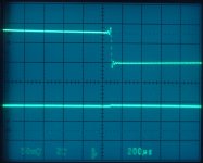
P.S. jwb once contributed a measurement for 25mA load step (top trace). Bottom trace is the reaction of the reg (V1 style).
Attachments
I put some effort in simplifying and improving v2. Hopefully this is my last(ish) version, ladies and gents, v2c.
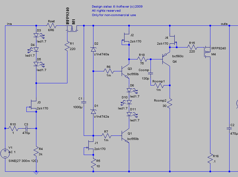
I have built the prototype and it works. Check out the output impedance. Ripple rejection that comes along the input is as good as before. Stability is set via the high frequency compensation components Ccomp, Rcomp1, and Rcomp2.
In other news, I built a mosfet based active load and tested v1, v2, v1.5, v2c. For a phono preamp, which has very little if any varying load, v1 will be all that you need. It is a clean circuit and can't be beaten, IMHO. salas, I have to congratulate you for what is probably the best regulator from many points of view. There are many details and I have run extensive tests in the last few days, I said these things from that experience.
Some people might want wide bandwidth low output impedance, and I put a lot of effort into coming up with something that would do that. v2c is the latest result that addresses that, and it is not only simulation, I have actually built it in tested it.
And please, would anybody comment, can it be improved? Anything looking wrong?
Does not look to have something wrong to me. I see that you got it simpler than before and that is only good. Its only that the compensation values must be finalized for a given pcb. To retain the extra performance with reliability, its layout, BOM, and compensation must be carved in stone. Of course V1 is the low parts count workhorse that can tolerate much for layout and components, and should be OK for most applications, but this V2 deluxe can prove its worth in driver situations or headphone preamps where there will be a lot of swing, since its buffered among other things. Or be the perfectionist's choice. Just that. Congratulations.
- Status
- This old topic is closed. If you want to reopen this topic, contact a moderator using the "Report Post" button.
- Home
- Amplifiers
- Power Supplies
- The simplistic Salas low voltage shunt regulator