After a loooooooooooooooooooong struggle finally
I 've got a pair of vifa P17WJ and D27's...
Next question is what to do with them...
I am thinking of a floorstander off the moment and later might do a TL...
mucking around with software ...these are the alignments i got...
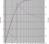
1) 25L tuned to 39hz
2) 22L tuned to around 37hz.
Question is which alignment should i choose...
ajju.
I 've got a pair of vifa P17WJ and D27's...
Next question is what to do with them...
I am thinking of a floorstander off the moment and later might do a TL...
mucking around with software ...these are the alignments i got...
1) 25L tuned to 39hz
2) 22L tuned to around 37hz.
Question is which alignment should i choose...
ajju.
Attachments
And
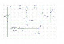
The P17 starts rolling off at around 2K and the D27 at around 1k
So i plan to cross them over at around 2k...and i intend to design and execute the crossover by myself..
I am planning to put a second order section for the tweeter and a first order section for the lpf...
I've tried simulatiing something in SPICE although wont be close to real system...
can someone comment on the results...
This is the crrossover i've been simulating......
Attachments
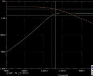
Now in the spice simulation, if i reppace the simple load resistor (the Speaker) with a simple model of the speaker will the results be more predictible...?
If so does any one have a model ready which i can just drag and drop and change the values...!!
Should be interesting...
If so does any one have a model ready which i can just drag and drop and change the values...!!
Should be interesting...
try this cabinet or similar :
http://home.hetnet.nl/~geenius/Tempo.html
with this crossover and d27 mods:
http://www.audiodiycentral.com/sd200_johnk.shtml
I like overdamped reflexes that can utilise room gain.
sreten.
http://home.hetnet.nl/~geenius/Tempo.html
with this crossover and d27 mods:
http://www.audiodiycentral.com/sd200_johnk.shtml
I like overdamped reflexes that can utilise room gain.
sreten.Attachments
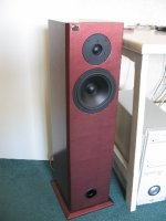
maartentje said:Hi, this is my Vifa Speaker if you want i have schematic of the filter and the wood.
Sorry for my english....
Maarten
This is definitely something I'd like to build in the future.
Please post your schematics.ajju said:Now in the spice simulation, if i reppace the simple load resistor (the Speaker) with a simple model of the speaker will the results be more predictible...?
If so does any one have a model ready which i can just drag and drop and change the values...!!
Should be interesting...
Yes, I'd say you *must* replace the load resistance with a better model so you see the results on the computer rather than in the real thing...
You can ignore the RML component, and the others can be calculated from the T/S parameters.Here is a good model of a driver, it will change a bit in a box, but usually not at frequencies which are important for the crossover design.
Attachments
Svante said:
Here is a good model of a driver, it will change a bit in a box, but usually not at frequencies which are important for the crossover design.
Won't this give results that ignore baffle step ?
sreten.The P17 starts rolling off at around 2K and the D27 at around 1k
So i plan to cross them over at around 2k...and i intend to design and execute the crossover by myself..
I am planning to put a second order section for the tweeter and a first order section for the lpf...
I've tried simulatiing something in SPICE although wont be close to real system...
can someone comment on the results...
This is the crrossover i've been simulating......
If it helps, here's some recent P17 measurements I took, averaged over several current units after breakin.
Fs: 46.17 Hertz
Qts: 0.41
Qes: 0.60
Qms: 1.28
Vas: 21.93 l
Re: 5.83 ohms
Le: 0.92 mH
SPL: 87.39 dB 1w/1m
BL: 6.35
Infinite baffle frequency response curve:
http://home.new.rr.com/zaph/audio/P17WJ00-08-sample1.gif
This driver doesn't have the smooth rolloff that everyone seems to think. Also note that it has changed slightly over the near-20 years it's been available. There actually was a time when it was a little smoother than it is now. Some older crossovers, even if well designed, don't work as well as they used to and end up having a little glare in the lower treble precisely because they don't have the smooth rolloff they used to.
First order won't work very well with this driver. I recommend 3rd order electrical, with the first series inductor enlarged to do most of the baffle step compensation work. Final acoustical rolloff will be closer to 2nd order if you don't use a zobel. If you do use a zobel and tweak the values a bit, you can get close to a 4th order rolloff.
The D27 is pretty close to Vifa's spec sheet, provided it's a new model. For a couple years Vifa had problems with the D27 having too high a Fs. It's been resolved in current models but I sure wouldn't want one that's a year or two old. If you have the D27 with the rear chamber, a 2khz crossover point may be borderline ok. If you have the one without the rear chamber, I'd bump it up to at least 2.5khz and 4th order acoustical rolloff. This tweeter sounds great but it gets harsh fast if crossed over too low.
All IMHO based on my experience with these drivers.
many thanks..!
Wow....this is really encouraging....
good to have so many references....
Btw, I could have used an available design for the crossover/baffle...but rather like it the DIY way...were u do A-Z all by yourself...Know its a tough ask but still...i think there is something very satisfying in that...thats why i've started from scratch and am looking forward to a lot of help from the guru's....
Sorry to say, but at times all of you might need to be a lilttle patient as chances are high that i might not understand things first go... And the progress on the project might be a little slow as i'm a bit busy at work..!
Ok...
So to sum it up ....this is something which i've thought off...a lil ambitious...
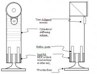
I'm not planning to make a conventional baffle...I will post a drawing of what i plan to do some time later...I'm planning to juggle around some PVC pipes to start with(It is not gong to be a transmission line like Kneadle's project)....i've got some 6.5 inch pvc pipes lying around...so would use them...the design is based on something i've done before...i liked the results..so planning to do the same way...so this might be a bit unconvetional... the P17 will be mounted in the cylindrical pipe...
Its going to be a reflex loaded design...with time alligned driver placements.....
but there are a lot of issues that i for see with the approach....
1) how to reinforce the pipe....
(there are two options...One is to provide cylindrical sections of the same PVC pipe and stick them to the inside of teh pipe at
random spacing to increase stifness and reduce low frequency oscillations...
2) Coat the inside of the pipe with a layer of rubber or the dense compound used to coat the underbody of SUV's and similar mud pluggers... (dunno the brand name) Its pretty thick and rubbery..
3) provide diametrical sections of MDF from top to bottom....small pieces say around 1" wide...and rotating by an angle every few
cm's...so that the final structure of the bracing inside follows a helical pattern..
4) How to make the PVC pipe joints strong...!!
5) Since it is going to be a tall design, how to prevent it from toppling over...!
Regarding the shape.
1) Will the tube resonate at its natural frequency...
2) how to get rid of this resonance and how serious is it going to be..?
3) Will the whole thing behave as a TQWT, all though that is not the intention...!
4) Looking at the diagram, I believe Baffle step compensation wouldnt be required in the crossover. Is that so.
Svante:
Thanks for the equivalent circuit....I'll try integrating it.
Sreten, zaph:
Many thanks for the inputs...
i'll get back to work with this....
should be really interesting...will keep you all posted about the progress..though it might be a bit sluggish..
ajju.
Wow....this is really encouraging....
good to have so many references....
Btw, I could have used an available design for the crossover/baffle...but rather like it the DIY way...were u do A-Z all by yourself...Know its a tough ask but still...i think there is something very satisfying in that...thats why i've started from scratch and am looking forward to a lot of help from the guru's....
Sorry to say, but at times all of you might need to be a lilttle patient as chances are high that i might not understand things first go...
And the progress on the project might be a little slow as i'm a bit busy at work..!Ok...
So to sum it up ....this is something which i've thought off...a lil ambitious...
I'm not planning to make a conventional baffle...I will post a drawing of what i plan to do some time later...I'm planning to juggle around some PVC pipes to start with(It is not gong to be a transmission line like Kneadle's project)....i've got some 6.5 inch pvc pipes lying around...so would use them...the design is based on something i've done before...i liked the results..so planning to do the same way...so this might be a bit unconvetional... the P17 will be mounted in the cylindrical pipe...
Its going to be a reflex loaded design...with time alligned driver placements.....
but there are a lot of issues that i for see with the approach....
1) how to reinforce the pipe....
(there are two options...One is to provide cylindrical sections of the same PVC pipe and stick them to the inside of teh pipe at
random spacing to increase stifness and reduce low frequency oscillations...
2) Coat the inside of the pipe with a layer of rubber or the dense compound used to coat the underbody of SUV's and similar mud pluggers...
(dunno the brand name) Its pretty thick and rubbery..3) provide diametrical sections of MDF from top to bottom....small pieces say around 1" wide...and rotating by an angle every few
cm's...so that the final structure of the bracing inside follows a helical pattern..
4) How to make the PVC pipe joints strong...!!
5) Since it is going to be a tall design, how to prevent it from toppling over...!
Regarding the shape.
1) Will the tube resonate at its natural frequency...
2) how to get rid of this resonance and how serious is it going to be..?
3) Will the whole thing behave as a TQWT, all though that is not the intention...!
4) Looking at the diagram, I believe Baffle step compensation wouldnt be required in the crossover. Is that so.
Svante:
Thanks for the equivalent circuit....I'll try integrating it.
Sreten, zaph:
Many thanks for the inputs...
i'll get back to work with this....
should be really interesting...will keep you all posted about the progress..though it might be a bit sluggish..
ajju.
Attachments
Hi, this is my Vifa Speaker if you want i have schematic of the filter and the wood.
Thanks Maarten, this should be a good reference...Please let me know if we have to take this offline.
ajju
Sreten :
Interesting thought. Will explore the possibility..
Couple of questions...
1) If i have to re-tune the port how easy is it going to be.
2) Since the weight of the speaker is off axis i need to lower the
centre of gravity of the whole unit or provide a large base.
I had thought of putting a sandfill as indicated in the diagram...
How do i manage that if i were to use the centre of the base
as a part of the flare port.
ajju
By fixing the base inside the speaker you can make the base the centre of the reflex port and exploit its flare shape
Interesting thought. Will explore the possibility..
Couple of questions...
1) If i have to re-tune the port how easy is it going to be.
2) Since the weight of the speaker is off axis i need to lower the
centre of gravity of the whole unit or provide a large base.
I had thought of putting a sandfill as indicated in the diagram...
How do i manage that if i were to use the centre of the base
as a part of the flare port.
ajju
- Status
- This old topic is closed. If you want to reopen this topic, contact a moderator using the "Report Post" button.
- Home
- Loudspeakers
- Multi-Way
- P17WJ and D27TG into a floorstander-advice.