ajju said:Svante,
heres is a zoomed graph...
ajju
Erhh... Where?
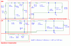
Anyway, the component values seem OK, the Fs = 1/(2pi*sqrt(CL)) = 37 Hz and Qms = R/(2pi*fs*L) = 1.5 from the values in the diagram. Re and voice coil impedance is also OK.
There *should* be a peak in the impedance of 18.8+5.8 ohms at 37 Hz. Does the program model the impedance from the diagram, or do you enter the diagram separately in some way?
Many thanks for the review Svante...
Ok...next step..integrating these into the X-over...And see how they show up..
that will be tomorrow...its past 2am here... and need another 20 min drive to get home..
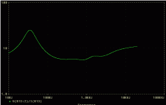
No i force the impedence to be calculated...
basically from the node parameters Pspice calculates...
so i basically add this to the graph..and bingo u have the impedence plot..
X ~= V(R3:2)/I(R1)
Voltage at node/Current at node after the source resistance.
thats how i go about it..!
thanks
ajju
Ok...next step..integrating these into the X-over...And see how they show up..
that will be tomorrow...its past 2am here...
Does the program model the impedance from the diagram, or do you enter the diagram separately in some way?
No i force the impedence to be calculated...
basically from the node parameters Pspice calculates...
so i basically add this to the graph..and bingo u have the impedence plot..
X ~= V(R3:2)/I(R1)
Voltage at node/Current at node after the source resistance.
thats how i go about it..!
thanks
ajju
ajju said:
Sreten:
Is the reference above to two drivers which are very similar, operating together..? Say 2 6" with same specs operating in tandem..!!
Actually I think sreten has got this a bit backwards. I'd like his (and anyone else's) comments on the following:
Consider two drivers working together. I will now explain what happens in two different ways.
1. They each get half of the total power. By superposition of the soundfields the sound pressure will be twice as high as if one speaker was disconnected. Twice as high sound pressure leads to *four* times the acoustic power. The efficiency has actually doubled by having two drivers operating near each other.
2. The acoustic power delivered by one driver is proportional to the force acting on the cone (from the air) multiplied by the displacement per unit of time. P=F*x/t. The force is proportional to the (sound) pressure at the cone. If both drivers are connected, the pressure at the cone will double, and each driver will deliver twice the acoustic power that it did alone. Net power = 4 times that of one driver. Again a doubling of the efficiency.
So far the efficiency issue. Now to simulating crossovers.
When two sound sources play simultaneously, their sound pressure fields are simply added (superimposed). This can lead to increased efficiency, but that is not the main point here.
The main point is that adding the two signals that taking the two signals that appear at the loudspeaker terminals, applying the drivers' transfer functions and adding these signals will give the exact right result. We don't need to think about the increased efficiency that follows the acoustic coupling between the drivers, it is automatically included in the addition of signals.
Take the L/R filter as an example. The output of the filter is 6dB down in each branch. This corresponds to a halved voltage, and adding these two halves, will end up in a whole. Adding two halved sound pressures will also end up in a whole. It's the same thing!
Hi Guys,
I am very very sorry i did not replay you message's i hate a problem with my girl friend its over.....
I have more time for my audio tommorow morning i scan every thing about my Vifa Floorstanding Super speaker
 its sound very nice with my new DAC and my JLH amplifier....
Sorry for my english....
Maarten
I am very very sorry i did not replay you message's i hate a problem with my girl friend its over.....

I have more time for my audio
Sorry for my english....
Maarten
Svante said:
Actually I think sreten has got this a bit backwards. I'd like his (and anyone else's) comments on the following:
Consider two drivers working together. I will now explain what happens in two different ways.
1. They each get half of the total power. By superposition of the soundfields the sound pressure will be twice as high as if one speaker was disconnected. Twice as high sound pressure leads to *four* times the acoustic power. The efficiency has actually doubled by having two drivers operating near each other.
2. The acoustic power delivered by one driver is proportional to the force acting on the cone (from the air) multiplied by the displacement per unit of time. P=F*x/t. The force is proportional to the (sound) pressure at the cone. If both drivers are connected, the pressure at the cone will double, and each driver will deliver twice the acoustic power that it did alone. Net power = 4 times that of one driver. Again a doubling of the efficiency.
So far the efficiency issue. Now to simulating crossovers.
When two sound sources play simultaneously, their sound pressure fields are simply added (superimposed). This can lead to increased efficiency, but that is not the main point here.
The main point is that adding the two signals that taking the two signals that appear at the loudspeaker terminals, applying the drivers' transfer functions and adding these signals will give the exact right result. We don't need to think about the increased efficiency that follows the acoustic coupling between the drivers, it is automatically included in the addition of signals.
Take the L/R filter as an example. The output of the filter is 6dB down in each branch. This corresponds to a halved voltage, and adding these two halves, will end up in a whole. Adding two halved sound pressures will also end up in a whole. It's the same thing!
ajju said:Sreten
are we missing something in ur previous post...
??
AFAI understand it if you sum the power and phase for each
driver you will get misleading results from a circuit simulator.
Even for the simple case of two drivers in series or parallel.
Both cases will give results -3dB lower than reality.
sreten said:
AFAI understand it if you sum the power and phase for each
driver you will get misleading results from a circuit simulator.
Even for the simple case of two drivers in series or parallel.
Both cases will give results -3dB lower than reality.
sreten.
Yes, but in the electric analogy, *power* isn't summed, but *voltages* (voltages being the analogue of (sound) pressure).
Take the linkwitz-riley filter which is 6dB down at the crossover frequency (and signals are *in* phase). -6dB equals half the voltage and 1/4 of the power. Now, if the voltages are added, we end up with a voltage of 1 which is OK. Adding the powers will give 1/2 or 3dB down, which is wrong.
You are right that the acoustic power is actually quadrupled when two drivers are playing side by side, even though the input is only doubled. But this is automagically taken care of when using analogies, since *voltages* (pressures) are added. Twice the voltage (pressure) makes four times the power.
This also works when the phases aren't equal if the voltages are treated as complex numbers.
Trust me, I teach this...
 (OTOH don't. Don't trust anyone just because he says so. But I'm pretty confident in that the above is right.)
 Hi Guys,
Here is some thing about my speaker....
http://zeeuw.inborn.net/maarten/vifa.htm
I hope you like it..
Maarten
Here is some thing about my speaker....
http://zeeuw.inborn.net/maarten/vifa.htm
I hope you like it..
Maarten
Hello Maarten
thankyou for your schematics
what am i missing
the picture one the first page of this thread has the port on the lower bottom of the speaker, which is also on the bottom in your schematics.
however is that an internal divider i see in the speaker, why is the port placed on the bottom of the speaker if there is a divider,
it is a H brace? that would mean the internal volume would be way more than the recommended 10-30lt
i have found this design with the port in the top half of the box
and could be sand filled in the bottom chamber
but the crossover is a bit questionable
http://ca.geocities.com/danf001ca/old/vx2t_plans.jpg
rest of plans here:
http://ca.geocities.com/danf001ca/old/
edit: bloody geocities quota
http://members.iinet.net.au/~jacen/danfmirror/
Why don't you try an Active X/O. You can add baffle diffraction, have practically no insertion loss, minimal phase problems & it is 24db down at the crossover point.
Hey Sunil,
Nice to hear from you.!
Yes active is on the charts..but may be a bit later. In fact i might have some active X/O's lying around...need to check...i remember having done some State variable filters long time back....
around the TL074/84 or the NE5534 devices....dont remember exactly...
the big problem is i am a bit handicapped for all my tools/comp and old projects etc etc are at home...So i'll have to check next time i go there..
Tell me more..
What have u used...Which opamp...any specialities form BurrBrown or analog...??
what configuration do u have for the filters...? Any time/phase correction elements to go with it as well....?
should be mighty interesting...!
ajju
I agree that by interpreting a circuit simulators output correctly....
Yes Sreten,
We do agree with you. There are a lot of things which you cant model on a circuit simulator. But one needs to have something to start with (of course u have proven designs which can be taken and tweaked) but when it is done afresh,i presume some kind of modelling has to be done as a starting point.
Once a basic architecture is arrived at, it has to be tweaked in the real system to get close to the goal. As i understand a circuit simulator might be of great significance in looking at the impedence plots etc..so as to predict how difficult a load the final design is going to be for the amplifiers.
Moreover it is not always possible to get a straight line response without a lot of trial and error, and the simulation data should be of great help in this stage.
Here is some thing about my speaker....
nice...
many thanks marteen..
ajju
- Status
- This old topic is closed. If you want to reopen this topic, contact a moderator using the "Report Post" button.
- Home
- Loudspeakers
- Multi-Way
- P17WJ and D27TG into a floorstander-advice.


