Hi,
I'm about to finish a 2C34-PP stereo amp. project.
To pull some usefull Watts from the 2C34 dual-triode I has to be allowed to pull grid-current, about 10mA, hence the CF-drive.
Having so far only put the amp on a scope and a tone-generator and measuring output-power, I have to say I'm pleased with the measured 12W/8-Ohm and 16Watt/4-Ohm. As I don't have a distortion analyzer I used the scope to determine the onset of distortion; not the most precise way, I admit.
When the amp's connected to my stereo and a pair of B&W 685 Speakers (88dB spl/1m, 8 Ohm.) it performs very much as hoped and expected. Rich and controlled bass (NFB applied) clean highs and nice vocals.
Now, my question is if I can safely simplify the CCS-circuit? The Cathode Follower is supplied from a Constant Current Source as per schematic (one channel shown, CF, CCS and output only).
I simply want to reduce the use of 4x6.2Vz and 4x1N4148 in each reference-string for the CCS to one of each. Then to connect each of the four BC549-bases to the 1N4148 Anode. Also could the MJE340 bases be connected to the common point between just one pair of 31K/3K3 resistors? Possibly the current in the reference chain 31K/3K3/1N4148/6.2Vz should be higher if transistors are connected as suggested above?
What you can't see from the schematic is that the -82V supply for the CCS is stabilized and comming from a TL783.
As the amp. is already built and pretty much finished I don't want to rip it apart to experiment needlessly. That's the reason for my question as I know someone here will definately have the right ansver
If anyone's interested I'll of course upload the rest of the schematic and pictures.
rgds and thanks,
/tri-comp
Attachments
And cascoding with another device is only nominally harder. One extra device, LM317 or LM134 (depending on current) and one resistor. Probably less than half a euro in cost. I cranked out a lifetime supply of PCBs for these (90 PCBs for about $40), so they're very easy to implement.
Hi,
I'm about to finish a 2C34-PP stereo amp. project.
If anyone's interested I'll of course upload the rest of the schematic and pictures.
rgds and thanks,
/tri-comp
Yes please on the complete schematics!
Thanks
DN2540N5 depletion mode fet
The reason for not using that is I'm not familiar with it ...until now.
LM317 / LM134
Use of these chips with an I-O potential of more than 100V. I don't think so!
The 2C34 g1-to-g1 swing is around 150Vpp
Simple enough
You're right, it isn't all that complicated AND it's already put together and it's working. I was just wondering and possibly I'll make another amp just like this as I already have the laser-cut and bended chassis for it. If I do I'll want to implement any improvements/simplifications, if any.
rgds,
/tri-comp
LM317 / LM134
Use of these chips with an I-O potential of more than 100V. I don't think so!
The 2C34 g1-to-g1 swing is around 150Vpp
/tri-comp
http://www.audioxpress.com/magsdirx/ax/addenda/media/jung2779.pdf
Fig. 13C
The LM317 is cascoded using a DN2540N5 or IXCP10M45S, giving it the capability to handle 400+ volts.
The pre-amp/concertina circuit.
The power-supply circuit isn't quite ready for publication as I haven't yet decided if I'm going to run the 6AN8A fil's on DC.
One channel is fully finished and I'm transfering the other pre-amp/concertina from a rats-nest to final point-to-point assembly.
After that and installing the bottom-cover I'll know about hum-level and need for DC-filament.
rgds,
/tri-comp
Attachments
http://www.audioxpress.com/magsdirx/ax/addenda/media/jung2779.pdf
Fig. 13C
The LM317 is cascoded using a DN2540N5 or IXCP10M45S, giving it the capability to handle 400+ volts.
I've been trying to get my hands on IXCP10M45S but it's simply not available from any of my suppliers including RS-Components.
I would REALLY love to work with that!
/tri-comp
If to simplify, I would avoid stabilizing of a negative voltage if CCS is stable enough (as drawn on your picture)
That is something I've considered already as I've come across this suggestion in an old (50'ies I think) description of a cathode-driven PP-stage with a pentode-CCS. It was specifically stated that the stability of the negative supply isn't all that important.
I can easily remove the chip and see...
Not tonight, however but more likely over the week-end.
rgds,
/tri-comp
Why bother with an LM317 when the DN2540 is all you need? Ixys also makes a line of depletion mode fets, some with higher voltage capability. Get familiar with the DN2540 - it's a very nice tool to have in the line-up.
DN2540 makes a lot of sense.
I was downloading the spec's and it looks very interesting.
Also not available from RS-Components
I'll find it somewhere....
Thanx
/tri-comp
I would better use a pair of transistors than a chip, in terms of frequency bandwidth. Also, a resistor in series with CCS will help on the upper frequency end, to minimize rectification effect of RF noises.
Here is my version (IRF610 and 2SC1815 cascoded with LED string for voltage references)
2 CCS' with trimpots per board because I use paralleled GU-50 in right-handed mode.
http://wavebourn.com/gallery/gubernator/driveccs01.JPG
http://wavebourn.com/gallery/gubernator/driveccs02.JPG
Here is my version (IRF610 and 2SC1815 cascoded with LED string for voltage references)
2 CCS' with trimpots per board because I use paralleled GU-50 in right-handed mode.
http://wavebourn.com/gallery/gubernator/driveccs01.JPG
http://wavebourn.com/gallery/gubernator/driveccs02.JPG
Last edited:
Wavebourn, what you describe may be OK where the adjustability is needed, but for something like an active loade for a CF, a lot of elaborate messing around is not necessary.
An advantage of using the Supertex parts is that they appear (at least so far) to be pretty well matched on a lot-to lot basis, making selecting the current-setting resistor pretty simple. I got got some parts in from Mouser a few days ago, and the first two parts out of the two were as alike as peas in a pod, both requiring 200 ohms to set a drain current of 10 ma. The last batch was also pretty consistent.
You have the FET, the current-setting resistor (hooked to the source), and a 1k stopper resistor (hooked to the gate). That's all you need. Don't omit the stopper resistor, unless you like high-power VHF oscillators. I was trying to a select a current setting resistor for one of the TO-92 Supertex depletion mode parts with some clip leads, a resistor (the part, of course) and a bench supply. I left out the stopper resistor, and the fet oscillated violently enough to confuse the bench supply and raise a ruckus in an FM receiver running in the next floor up (I was in the basement). 1K shuts it up...
What I shown, is exactly load of CF that drives output right-handed triodes. Trimpots are added because I have 2 tubes in parallel, to adjust bias between them, they are not needed if driving a single triode.
You are right about stoppers, I already fixed the mistake. I forgot about them drawing PCBs.
You are right about stoppers, I already fixed the mistake. I forgot about them drawing PCBs.
Yes, you can use a slightly simpler CCS.
I routinely use a "Ring of Two" transistor CCS for CF loads. Usually an MJE340 + a BC547C + 3 resistors.
I only go to cascoded transistor for differential amp tails where I need the higher impedance and lower capacitance (maintain that high impedance to higher frequencies).
That maintaining of the CCS impedance to high frequencies is what lets down all of the LM317 and similar based CCS circuits and I'm sorry to tell all of you DN2540 fans that it is not that good in that respect either, although of all of the common "depletion mode mosfet" devices the DN2540 is the best for low device capacitance (or at least it was when I last did a datasheet comparison of readily available devices about 8 months ago, it is cetainly better than the 10M45 which is the other "usual suspect").
Cheers,
Ian
Last edited:
This is what I should have read before buildig the amp. 
http://www.audioxpress.com/magsdirx/ax/addenda/media/jung2779.pdf
Sorry, the file is too big for attaching here
Thanks for all the good pointers and opinions.
/tri-comp
http://www.audioxpress.com/magsdirx/ax/addenda/media/jung2779.pdf
Sorry, the file is too big for attaching here
Thanks for all the good pointers and opinions.
/tri-comp
Unless you're swinging a whole lot of volts I doubt that the ultimate in output impedance vs. frequency is needed for a CF current source. A depletion mode mosfet is a simple choice and works quite well. For more demanding applications like a tube plate load where lots of volts are swinging around, you could use a cascode of DN2540 with DN2540 (SY does this). If you want to save a bit of money, you can cascode a TO-92 2540 with its TO-220 big brother, as the TO-220 will be holding off practically all the voltage from its little brother. For the CF application, another possibility would be a ring of two with a small mosfet (lower capacitance) as the current source and a bipolar as the current sense element. There are more options than a cat has hair...
BTW, I wasn't all that impressed with a lot of the options presented in the Audio Express article. Search the web, and you can find some studies that present more viable options.
BTW, I wasn't all that impressed with a lot of the options presented in the Audio Express article. Search the web, and you can find some studies that present more viable options.
Last edited:
There are more options than a cat has hair...
Well I'll have to put a picture of my cat here. It developed flee-allergy and has removed almost all it's hair by constantly licking and cleaning, so that comparison doesn't hold with me!
The real problem here is that I'm no construction engineer but rather an electronics repair tech. I don't know a lot about dimensioning stages; the why and how. I do, however easily interpret the results of my dabblings; go or no-go. Reading tech doc's and understanding them isn't a problem but I really have to force myself when I start dimensioning. I can smell at 10 feet distance why the YSUS module in a LG plasma-TV went south etc, etc but construction is something different. A lifetime at the repair-end of things leaves marks
Still, I follow your inputs and understand the different directions that are suggested. My MJE340/BC549-string is probably not perfect at higher frequencies. I'll have to do more measuring to find out.
As this is my first tube-project ever, I'm still very pleased with the outcome. Who ever pulled 12W/8Ohm from a 2C34-PP at audiofrequencies?
Next project after this will be an EL34-PP/UL with Lundahl iron and no CF. The LTP will feature a CCS of some sort so the interest still stands.
rgds,
/tri-comp
Last edited:
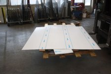
Here's a few pictures from the building of the amplifier.
Starting out with a raw sheet of stainless steel to be cut by a laser.
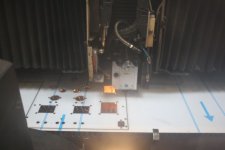
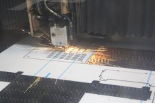
Probably not many have seen how it actually looks when the laser cuts.
Well, here's a chance to enlighten yourself
I needed to cut 3 different materials: steel, aluminum and plastic
All can be cut with a laser if the operator knows what he's doing and in my case I know the best!
Plastic bits, aluminum and stainless steel-plates are cut with a sheet-laser.
I also needed some way of mounting the electrolytic caps and I did't want to see them sticking up through the amplifier top-plate.
A capacitor holder/frame that takes up to 6 either Ø22mm or Ø25mm caps was drawn and cut. This time with a tube-laser and in regular rectangular steel-tubing. For not to squeeze the caps between all steel-frames the center-piece is made from plastic allowing for some elasticity when assembling the frame.
An aluminum 'heat-sink' plate was made where to place various components that needs heatsinking. Actually the 10 Ohm Cathode-resistors aren't all that hot, but it looks tidy when they are mounted on the plate. Also the LM317T regulator hasn't yet been put to use. It's for regulating DC for the 6AN8A fil's, but I don't yet know if that feature will be implemented. The main rectifiers are also put here but again, it's a bit overdone. I'm not drawing any serious current from these diodes (2ea. 15STH06FP). The plate also serves to mount a small piece of Veroboard with the negative supply transformer and regulation (TL783)
Feel free to ask whatever questions you have....
rgds,
/tri-comp
Starting out with a raw sheet of stainless steel to be cut by a laser.
Probably not many have seen how it actually looks when the laser cuts.
Well, here's a chance to enlighten yourself
I needed to cut 3 different materials: steel, aluminum and plastic
All can be cut with a laser if the operator knows what he's doing and in my case I know the best!
Plastic bits, aluminum and stainless steel-plates are cut with a sheet-laser.
I also needed some way of mounting the electrolytic caps and I did't want to see them sticking up through the amplifier top-plate.
A capacitor holder/frame that takes up to 6 either Ø22mm or Ø25mm caps was drawn and cut. This time with a tube-laser and in regular rectangular steel-tubing. For not to squeeze the caps between all steel-frames the center-piece is made from plastic allowing for some elasticity when assembling the frame.
An aluminum 'heat-sink' plate was made where to place various components that needs heatsinking. Actually the 10 Ohm Cathode-resistors aren't all that hot, but it looks tidy when they are mounted on the plate. Also the LM317T regulator hasn't yet been put to use. It's for regulating DC for the 6AN8A fil's, but I don't yet know if that feature will be implemented. The main rectifiers are also put here but again, it's a bit overdone. I'm not drawing any serious current from these diodes (2ea. 15STH06FP). The plate also serves to mount a small piece of Veroboard with the negative supply transformer and regulation (TL783)
Feel free to ask whatever questions you have....
rgds,
/tri-comp
Attachments
Last edited:
- Status
- This old topic is closed. If you want to reopen this topic, contact a moderator using the "Report Post" button.
- Home
- Amplifiers
- Tubes / Valves
- CF/CCS, can it be made simpler?