...still more
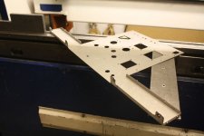
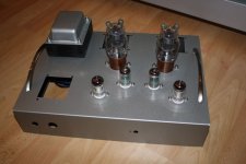
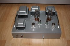
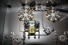
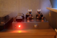
On the second picture you may notice that I don't have 6AN8A put in the front sockets.
I hadn't really decided to use them at that point.
Glad, I did")
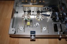
On the second picture you may notice that I don't have 6AN8A put in the front sockets.
I hadn't really decided to use them at that point.
Glad, I did
Attachments
Last edited:
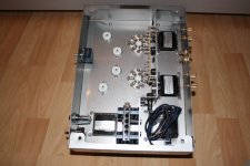
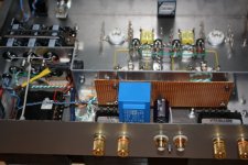
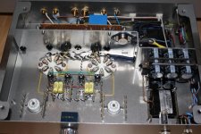
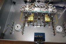
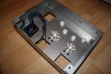
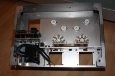
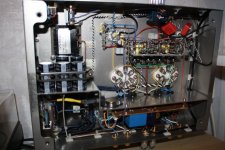
These are the latest pictures. Both pre-amp/concertina channels have now been finally wired and the rats-nest in the upper right corner is gone
I mostly only need to tidy up some screened input cables and the NFB cabling ...AND to decide about DC for 6AN8A fil's.
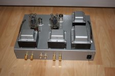
Yes, I do have a bottom cover and some feet for the amp
More pictures to follow once the work is fully done.
Of course also the power-supply schematics.
rgds,
/tri-comp
I mostly only need to tidy up some screened input cables and the NFB cabling ...AND to decide about DC for 6AN8A fil's.
Yes, I do have a bottom cover and some feet for the amp
More pictures to follow once the work is fully done.
Of course also the power-supply schematics.
rgds,
/tri-comp
Attachments
Last edited:
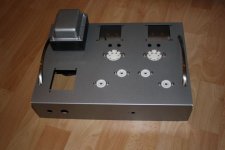
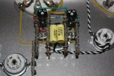
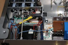
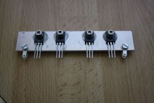
Looks very nice, except electrolytic capacitors on the same plate used for heatsink, and film capacitors on the convection path from MOSFETs.
The cap's aren't in thermal contact with the heat-sink at all.
The clamp-construction is solely held in place with the use of 2 stand-off's attached to the center plactic piece.
Film over mosfet's isn't happening. These are MJE340's
Anyway I get your point but the cap's are Vishay's 1813'. Shouldn't they be able to cope with modest heating?
BTW, the heat-sink isn't really 'taking the heat' because there is nothing to heat it until the LM317T starts cooking, if ever.
/tri-comp
To round this off I'll post the final schematics in case anyone wonders how it turned out in the end.
It turned out VERY good in fact. About 12Watt/8R and 16Watt/4R and sounding much louder.
Absolutely no hiss on open input and full volume. Hum very, very low. Barely noticable with speakers. On a headset it's there but gone when the music starts. Impossible to notice even with low music levels.
You won't believe how the opening scene of 'Top Gun' sounds in my B&W 685's. They're rather small but the SOUND...!!
Huey Lewis and Dire Straits really hit the low notes that before I didn't even now existed in the CD's.
So, for a 'first' I'm rather pleased
Thanks for all inputs and ideas.
rgds,
/tri-comp
Attachments
Yes please on the complete schematics!
Thanks
I saw in another thread that you have VT61A's on hand.
Did you ever find data on them?
They're suppose to be a steroid version of VT61 / 2C34 / RK34 etc.
My power-supply and output x-formers and will easily handle more watts than with the 2C34's and I found a supplier of the VT61A here in Europe.
The CF/CCS should also be up to it if I stay below 20mA g1-currernt in AB2.
Just don't want to buy the VT61A's w/o curves and data.
Help,
rgds,
/Torben
Hi,
Thanks a lot.
Only 18 months passed ...
Glad you notiched, though.
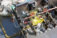
I would like to explain what my initial question in this posting 'CF/CCS, can it be made simpler?' means.
I was actually asking if a single resistor/zener reference-chain 33K/3.3K/1N4148/BZX85C6V2 may be used as a ref. for all 4 CCS' ?
I.e. all 4 x Basis of MPS-A06 connected to 1N4148/Anode and all 4 x Basis of MJE340 connected to 33K/3.3K midpoint.
This would save me 3 x 2.2ma of reference-chain current of the chains no longer needed. (Unless I have to up the existing current of the remaining common chain)
That's somewhat important as the small negative-supply PCB-transformer I used for this amp is running a little hot.
Also the point-to-point wiring will be simpler and more elegant.
rgds,
/tri-comp
Thanks a lot.
Only 18 months passed ...
Glad you notiched, though.
I would like to explain what my initial question in this posting 'CF/CCS, can it be made simpler?' means.
I was actually asking if a single resistor/zener reference-chain 33K/3.3K/1N4148/BZX85C6V2 may be used as a ref. for all 4 CCS' ?
I.e. all 4 x Basis of MPS-A06 connected to 1N4148/Anode and all 4 x Basis of MJE340 connected to 33K/3.3K midpoint.
This would save me 3 x 2.2ma of reference-chain current of the chains no longer needed. (Unless I have to up the existing current of the remaining common chain)
That's somewhat important as the small negative-supply PCB-transformer I used for this amp is running a little hot.
Also the point-to-point wiring will be simpler and more elegant.
rgds,
/tri-comp
- Status
- This old topic is closed. If you want to reopen this topic, contact a moderator using the "Report Post" button.
- Home
- Amplifiers
- Tubes / Valves
- CF/CCS, can it be made simpler?