hi,
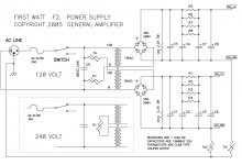
i want to build an F2 (or should that moniker be reserved for the originals made by the big man himself? i should say F2 clone). i have a question regarding the PSU. the original schematic in the service manual shows a toroid with dual 18v secondaries. can replace this with two 0-18 EI transformers? is it possible to use a single, centre tapped EI transformer? i am asking because toroidal transformers are very expensive in india, about 2.5x the cost of a good EI transformer. if i use two transformers i am thinking of going with 350VA each. do you think i need to increase this?
thanks
mymindinside
according to my tricky memory - F2 have 75W dissipation per channel , so even 250VA xformer per channel is approaching overkill ...... but more is always merrier , at least in xformer department ;
you can use CT xformer - connecting CT to gnd and using just two diodes (one from each sec. end to + ) to have full-wave rectification
or even better - use two xformers ( from 250VA and up) , each having just one 18Vac secondary
Papa's PSU is sort of dual mono PSU with common core and primary
you can use CT xformer - connecting CT to gnd and using just two diodes (one from each sec. end to + ) to have full-wave rectification
or even better - use two xformers ( from 250VA and up) , each having just one 18Vac secondary
Papa's PSU is sort of dual mono PSU with common core and primary
thanks Zen mod,
if i go with two transformers (which is not more expensive for me than going with one, larger one) what type of rectification would i use? a bridge with the - connected to ground?
Also, with this xformer size, will i need a separate soft start circuit aside from what is already in the schematic (in the form of the thermistors)?
Last edited:
hello Mr Pass,
will definitely try the Jfets once the amp is up and running.
my enthusiasm has taken a hit in the past few days though, when i was told in another thread that none of the heatsinks i have available are good enough for the F2. just to confirm, the dissipation is 75w for 2 channels?
apparently the heatsinks i posted did not have a thick enough base so the thermal conduction from the device was effective only across a small area.
i would really appreciate it if you had a look at the thread and shared any insights,
and of course, merry christmas to you and your loved ones!
mymindinside
p.s. the thread is located here
I read the thread in regards to the heatsinks you are looking at. One thing you can do to help spread the heat more evenly across the heatsink would be to attach the mosfet directly to a piece of copper that covers most of the flat face of the heatsink. Then put the insulator between the copper plate and the aluminum heatsink. Copper has a higher thermal coefficient, so it will pull heat away from the mosfet (or any other device) quicker. And having the transistor tied directly to the copper, then isolating the copper pulls the heat from the transistor faster.
Peace,
Dave
Peace,
Dave
thanks Zen mod,
if i go with two transformers (which is not more expensive for me than going with one, larger one) what type of rectification would i use? a bridge with the - connected to ground?
Also, with this xformer size, will i need a separate soft start circuit aside from what is already in the schematic (in the form of the thermistors)?
yes - full Graetz , with - to gnd
you can use one NTC for both xformers
...... just to confirm, the dissipation is 75w for 2 channels?
......
yes ...... 75W for two channels ........ and double it

I wrote already - 75W per channel
Hi,
i went out to buy the parts yesterday and realized that the only 3W resistors available are inductive wirewounds. The alternative is 2W carbon types. Can i use a combination of these in the F2? can someone please guide me through which type i should use for which position...
thanks in advance
am attaching the schematic below
cheers,
mymindinside
Attachments
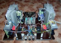
Hi, it's my F2 clone prototype Transformers 2x 100VA (18V-4A). In final version There are toroidal transformers in final version. More photos on my webpage.
Voigt Pipes
Transformers 2x 100VA (18V-4A). In final version There are toroidal transformers in final version. More photos on my webpage.Voigt Pipes
Attachments
Last edited:
Hi again,
in continuation to the resistors question; i had meant to post the amplifier schematic, but by mistake posted just the psu schematic. That is why DougL commented only about the PSU resistors.
i am attaching the amplifier schematic now, could you please have a look and see if i can use wirewounds throughout?
thanks
mymindinside
Attachments
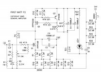
just those which Papa labelled as WWND can be plain wirewound , where Papa also accounted on their inductance .
all other resistors must be non-inductive , be it Metal Oxide or wirewound
non-inductive wirewounds aren't usual rectangular white ones , which you can buy everywhere
all other resistors must be non-inductive , be it Metal Oxide or wirewound
non-inductive wirewounds aren't usual rectangular white ones , which you can buy everywhere
So i decided to parallel 2 2W carbon resistors because i just cant find 3W non inductive ones. can you please tell me if the values are close enough to the originals or if i am in trouble.
instead of 1R i am using 2 x 2.2R
instead of 47R i have 82R and 100R
and instead of 0.47R i have 2 x 1R
is this ok?
I finally decided to order a toroidal transformer because i found a local source where it was working out cheaper than a EI transformer of the same VA. i have ordered a 625VA xformer with 2 x 18v secondaries. i am paying INR 3,200 which is about USD 67.
Heatsinks are ordered and will be here in 10 days.
the only problem is that i cant find a nice electrolytic for C3 (the output cap). am going with 3 x 4700uf electrolytics made by an Indian company called Keltron. hope it is decent. i am bypassing it with a 1uf metallized polyester cap. that was the best i could find.
anyway, will post progress as it is made, meanwhile any help with the resistor issue would be great. my only alternative is inductive wirewounds.
thanks,
mymindinside
So i decided to parallel 2 2W carbon resistors because i just cant find 3W non inductive ones. can you please tell me if the values are close enough to the originals or if i am in trouble.
instead of 1R i am using 2 x 2.2R
instead of 47R i have 82R and 100R
and instead of 0.47R i have 2 x 1R
is this ok?
I finally decided to order a toroidal transformer because i found a local source where it was working out cheaper than a EI transformer of the same VA. i have ordered a 625VA xformer with 2 x 18v secondaries. i am paying INR 3,200 which is about USD 67.
Heatsinks are ordered and will be here in 10 days.
the only problem is that i cant find a nice electrolytic for C3 (the output cap). am going with 3 x 4700uf electrolytics made by an Indian company called Keltron. hope it is decent. i am bypassing it with a 1uf metallized polyester cap. that was the best i could find.
anyway, will post progress as it is made, meanwhile any help with the resistor issue would be great. my only alternative is inductive wirewounds.
thanks,
mymindinside
2R2 II 2R2 - good enough instead of 1R
for 47R - use 2 paralleled of 100R
two 1R paralleled instead of 0R47 - good
regarding bypass - I'm proponent of cheap and great solution - use motor-run cap , from 20uF upwards ; they're of great - industrial quality - and you can hardly beat them with any audiophool grade cap .
Thanks ZenMod for the quick reply. i am feeling a bit better, the parallel solution seems workable.
now i am waiting for the boards. i ordered them from Peter Daniel and he said he would ship them out today. the semiconductors i ordered (from tech-diy) took about 2 and a half weeks to reach. i think that the boards will take around the same time.
i am a bit impatient because the sachikos i will be powering with this amp are ready and i cant wait to listen to them!
cheers,
mymindinside
- Status
- This old topic is closed. If you want to reopen this topic, contact a moderator using the "Report Post" button.
- Home
- Amplifiers
- Pass Labs
- F2 PSU with 2 EI transformers?