I am hit with another parts problem:
I looked at the datasheet for the NTC thermistors and it says that cl60 types have a dia. of about 20mm. it mentions cl110 and cl120 types, which are also 10 ohms at ambient but have lower current ratings (3.2 and 1.7 amps respectively). they are smaller with a dia. of 10mm. i measured mine and the dia. is about 12mm. the shop that i bought them from did not know the designation or the current rating but only sold them as 10 ohm thermistors. i suspect that they are not cl60 but one of the lower rated ones. unfortunately this is all i have available. can i parallel thermistors of a different value to get enough current rating? i am using a 625VA toroid and want to avoid the large inrush current at turn-on.
any help is much appreciated folks
thanks
mymindinside
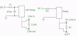
If you have a relay available that can handle the rated AC current, and rated at the B+ current or below, you can do something like shown. The version on the right is the simplest case. Just adjust the series resistor to the relay coil, so that it switches when the B+ reaches about 75% of it's final value. The resistor in series with the AC line, can be anything from a CL-XX to a regular power resistor of 10-100 ohms.
Sheldon
edit: This approach has the advantage of taking the AC series resistance out of the circuit after start up.
Sheldon
edit: This approach has the advantage of taking the AC series resistance out of the circuit after start up.
Attachments
Last edited:
Thanks sheldon.
to be perfectly honest i am not confident enough to attempt this. i have never used a relay in any project.
what type of relay would i need?
what should the wattage of the resistors be?
what is PT in the schematic?
what is the switch that is placed before the relay? and also what is the connection that goes from the AC line to the other side of this switch?
sorry for the newbie questions, but i dont want to fry anything (and mostly myself)
thanks,
mymindinside
what type of relay would i need?
what should the wattage of the resistors be?
First, the relay must be rated for continuous duty. It also must be N/O, or normally open type. Then are two separate voltage/current ratings to consider; the actuating (solenoid) coil, and the contacts.
Coil: To be used as shown, the coil should be rated at about the B+ voltage, or below. Let's say your B+ is 24V, and your relay is rated for 24VDC, You can connect the B+ across the coil. Essentially all relays will switch well below the coil rating. A 24V relay might switch at 15V or so. If you want the B+ to be closer to 24V, you can put a resistor in series with the coil. This will act as a voltage divider to the coil. You can play with this value until the relay switches at say 20V. I'd leave a few volts margin. If you put too much resistance in series, the relay may not actuate reliably. To calculate the resistor wattage rating, just measure the coil resistance. Calculate it's current at its rated voltage. That's the maximum current your resistor will see. From that you can calculate a safe wattage.
If you want to use a lower voltage relay, say one with a 12V coil, then you will have to use a series resistor to the coil, with a resistance at least equal to the coil resistance.
Contacts: These need to be rated for the AC current and voltage at the primary of your transformer. Let's say you have 240AC line voltage, 24V secondaries, and the amp draws a maximum of 1 amp. You'd need the contacts rated for 240VAC, of course. At 1 amp DC, the AC current will be 0.1A for this example. However, your charging currents will be higher, so you will want a higher rating. I'd go with something like 5-10A, which is easy to find.
If you want to slow down the relay even more, you can use the configuration shown on the left. The series resistor and cap form an RC circuit that has to be charged up before the coil sees enough voltage to actuate the relay. Bigger cap, slower response.
what is PT in the schematic?
what is the switch that is placed before the relay? and also what is the connection that goes from the AC line to the other side of this switch?
PT is power transformer primary.
The switch that is shown on the schematic is the relay switch itself. The box above it represents the actuating coil. This relay switch is inline with the line input to the power transformer primary.
Sheldon
Last edited:
Just as an uber-simple solution, can't i just replace the relay with a manual switch, and close this switch a few seconds after i apply power to the transformer? i am a bit paranoid about long term reliability and of what would happen i a fault condition. i fear that if the relay does not close in time, or sticks open, then the resistor in line with the AC would be overloaded very soon. in this case it is possible that the melted solder or the seperated component leads will touch the chassis, making it live.
is there any issue with having a manual switch? apart from the nuisance value of throwing two switches of course.
cheers,
mymindinside
is there any issue with having a manual switch? apart from the nuisance value of throwing two switches of course.
cheers,
mymindinside
You can do that, but I wouldn't recommend a manual switch.
Relays are pretty easy to find in lots of discarded gear. Even some automotive relays have contacts rated for up to 400V (sometimes hard to find the ratings for a particular model, however).
BTW, if you think the CL's you have are a bit small, yes you can parallel them.
Sheldon
Relays are pretty easy to find in lots of discarded gear. Even some automotive relays have contacts rated for up to 400V (sometimes hard to find the ratings for a particular model, however).
BTW, if you think the CL's you have are a bit small, yes you can parallel them.
Sheldon
Let me put it this way: I wouldn't do a manual switch. I'd forget to have it on or off at the appropriate time, and if someone else wanted to use the system, it's one more thing to explain. A relay is simple. And it's really no more trouble than wiring in an extra switch. Then you forget about it.
Technically, two manual switches will function. Your amp, your call.
Sheldon
Technically, two manual switches will function. Your amp, your call.
Sheldon
Hi,
if your use resistors to reduce the start up current then you MUST bypass the resistors very soon after switch on to prevent them overheating. try a timer with 100ms to 300ms delay.
If you use Thermistors you have the option of a quick bypass or a slower bypass. The Thermistor will adjust it's resistance to suit the current passing through it.
- Status
- This old topic is closed. If you want to reopen this topic, contact a moderator using the "Report Post" button.
- Home
- Amplifiers
- Pass Labs
- F2 PSU with 2 EI transformers?