Intro: Front channels go to a pair component speakers, rear channels are bridged to one sub.
So I was messing with stuff in my trunk and unplugged my rear input rca cables and to my suprise my sub kept playing. I thought at first the 'combine' switch was pressed which sends the front signal to the rear but it wasn't, and when I did press it in, the output to my sub seemed to double.
Any ideas on what might be messed up to allow the front signal to leak to the rear?
Also I was messing with the LP/HP switch for the rear channel, I could see the woofer moving in and out as I pressed the switch, when it is set to HP I measure 2mV of DC on the output, but on LP it is like 0.2mV, is that a problem? I have it set to LP right now since it is going to a sub.
further clarification of problem
Just to add to this, if I engage the hp filter for the rear channels,only sound from the rear inputs is used, but if the lp filter is engaged, somehow sound from the front inputs gets through to the rear channels.
I'll take any suggestions no matter how far fetched!
Just to add to this, if I engage the hp filter for the rear channels,only sound from the rear inputs is used, but if the lp filter is engaged, somehow sound from the front inputs gets through to the rear channels.
I'll take any suggestions no matter how far fetched!
Okay, finally got the amp out of my car.
All large 10 ohm resistors are good (10.5 ohms usually)
All Shields have about 20.8 ohms between them
No open traces that I can see
This is the really long amp, all rca's were plugged into the proper input, I've never spilled anything on it but since I bought the amp used, it could have had something spilled on it, but judging by the inside, doesn't look like it.
Not sure if this is related but might as well through it out there, when I was repairing the amp previously for a broken leg on the large inductor, I somehow fried the 108a muting transistor on the left rca output, maybe by misaligning the pre-amp board. So I pulled up the 'gate' leg on the 108a for both the R and L rca output and the amp started to play again. The drain and source of the transistors are still soldered to the board, so maybe the faulty transistor is doing something?
My other idea is that the hp/lp circuit is messed up since there is good channel separation when in hp mode, but in lp mode the front signal is getting to the rear output.
Pull the 2 muting transistors near the output RCAs to see if it changes the symptoms.
You should check the switches in both positions to confirm that all of the contacts are in good condition. You should read very near 0 ohms for each set of contacts. Let me know if you don't know how to check them and need more information on the internals of the switches.
You should check the switches in both positions to confirm that all of the contacts are in good condition. You should read very near 0 ohms for each set of contacts. Let me know if you don't know how to check them and need more information on the internals of the switches.
I apologize for the long break, but I got busy with other things and didn't get a chance to look at the amp in a while.
I replaced the muting transistors, so the rca outputs now work. I checked the connections on the hp/lp switch. I've attached a pic of the connections. Let me know if I need to check it another way.
Also its seems that a bit of signal leaks to the rear channels from any input (not just fronts) when the switch is in low pass mode. So even if I connect a source to the right rear input, I will get a bit of sound coming out of the left and right rear output.
Attachments
If you read 0 ohms between those points, the switch looks like it's OK.
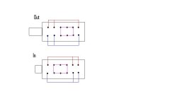
Use the following image as a guide when checking the switches. You only have to confirm that the sliding contacts are making a good connection between each of the two fixed contacts. This should save some time.
Use the following image as a guide when checking the switches. You only have to confirm that the sliding contacts are making a good connection between each of the two fixed contacts. This should save some time.
checked all the switches. They all start at zero and settle to .4 or .5 ohms. On one set of contacts on the -12db switch settles to 1 ohm sometimes, then 4 ohm, then 40 ohms, but it might because of my probes have really sharp points and its hard to hold them to the soldered spots on the bottom of the board.
I have an extech meter and have noticed that it bounces around a lot before settling on a value, wish I had a fluke.
I have an extech meter and have noticed that it bounces around a lot before settling on a value, wish I had a fluke.
yep, sound at about 1/2 volume will appear on the both rear channels, regardless of which input (front or rear, right or left) that I apply signal to. If I push the hp/lp switch for the rears, in high pass the sound doesn't get through, only in lp setting does it get through.
Some additional info:
the sound leaking to the rear channels is effected by the rear gain, and qbass switches, so I can make it softer or louder.
The rear channel rca outputs only output sound when a signal is applied to the rear rca inputs, there is nothing on the rear rca outputs when a signal is applied to the front rca inputs.
Okay, so I've tracing out the signal path on the top input board on my pc4100. I think I've figured out what each chip does. The are U1 through U5 from top to bottom. The connector J1 connects the board to the bottom main board, which has the rear lp freq control, qbass, and front and rear gain circuitry. Since the sound that leaks from the front to rear channels is effected by those controls, I'm pretty sure the problem is occurring on the top board.
Here is what I have been able to figure out for connector J1:
Pin 1 = connects to the other side of the 37k ohm resistors in the pic for both the rear channels shown in green, and the other side of the 37k ohm resistors that connect to the front channels shown in yellow. I believe this is the summed Rear signal to feed lp circuitry on bottom board but I'm not sure. Maybe the problem is somewhere in here.
Pin 2 = Rear lp signal output to connect to hp/lp switch
Pin 3 = Vcc for top board +15V
Pin 4 = Muting signal for rca output transistors -12V
Pin 5 = Left Front signal from U3 pin 7
Pin 6 = connects to rca input shields though 10 ohm resistor, also connects to the otherside of the vertical 10k ohm resistors as shown in pic in yellow and green.
Pin 7 = same as pin 6
Pin 8 = Right front signal from U3 pin 8
Pin 9 = Right rear signal from U3 pin 1
Pin 10 = Left rear signal from U3 pin 14
Pin 11 = Vee -15V
I know this might look like a mess, but I'm trying to put it all together. Couple thinks to figure out are:
1. On the combine switch, why such a rears have 43k ohm between output, whereas fronts only have 13k ohms. I checked this with the switch removed, and also checked that the switch works properly, it does.
2. Figure out the purpose of the resistors I boxed in yellow and green, which connect to pin 1 on the other side of 37k res and connect to pin 6 and 7 through 10k ohm res. This is true regardless of whether the combine switch is on or off.
Anyway, just thought I would get out some of the info I've been gathering and get some ideas on where to go next.
Also I have a better image, but it was too big, so I can email it to you so you can see it better
Attachments

input board
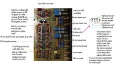
Okay, so I've tracing out the signal path on the top input board on my pc4100. I think I've figured out what each chip does. The are U1 through U5 from top to bottom. The connector J1 connects the board to the bottom main board, which has the rear lp freq control, qbass, and front and rear gain circuitry. Since the sound that leaks from the front to rear channels is effected by those controls, I'm pretty sure the problem is occurring on the top board.
Here is what I have been able to figure out for connector J1:
Pin 1 = connects to the other side of the 37k ohm resistors in the pic for both the rear channels shown in green, and the other side of the 37k ohm resistors that connect to the front channels shown in yellow. I believe this is the summed Rear signal to feed lp circuitry on bottom board but I'm not sure. Maybe the problem is somewhere in here.
Pin 2 = Rear lp signal output to connect to hp/lp switch
Pin 3 = Vcc for top board +15V
Pin 4 = Muting signal for rca output transistors -12V
Pin 5 = Left Front signal from U3 pin 7
Pin 6 = connects to rca input shields though 10 ohm resistor, also connects to the otherside of the vertical 10k ohm resistors as shown in pic in yellow and green.
Pin 7 = same as pin 6
Pin 8 = Right front signal from U3 pin 8
Pin 9 = Right rear signal from U3 pin 1
Pin 10 = Left rear signal from U3 pin 14
Pin 11 = Vee -15V
I know this might look like a mess, but I'm trying to put it all together. Couple thinks to figure out are:
1. On the combine switch, why such a rears have 43k ohm between output, whereas fronts only have 13k ohms. I checked this with the switch removed, and also checked that the switch works properly, it does.
2. Figure out the purpose of the resistors I boxed in yellow and green, which connect to pin 1 on the other side of 37k res and connect to pin 6 and 7 through 10k ohm res. This is true regardless of whether the combine switch is on or off.
Anyway, just thought I would get out some of the info I've been gathering and get some ideas on where to go next.
- Status
- This old topic is closed. If you want to reopen this topic, contact a moderator using the "Report Post" button.
- Home
- General Interest
- Car Audio
- PPI 4100 front input leaking to rear ouput