Since you've mapped it all out, drive two of the inputs with a signal (sine wave preferred or pink noise if you have to have the crossovers in the circuit) and measure the AC voltage on each output pin of the various op-amps. Make notes for the voltages and switch positions. At the point where you find signal (where there should be no signal), that would be the point you'd begin troubleshooting.
You should install shorting jumpers in the unused RCA input jacks.
You should install shorting jumpers in the unused RCA input jacks.
Unfortunately, I don't have access to a scope, sign gen, and power supply anymore (was using the one's at school), so I'll probably have to buy all that stuff, in order to do the testing, or find someone that has that stuff.
Perry, on a side note, I have a pc2150, that has an intermittent channel. I found when I push on the rca input, it comes and goes, so it was the source of the problem. I tried resoldering all the connections to the board and also tried to solder the bell to the metal posts (like in one of your pics) but I still have the problem. Do rca's go bad, do you think the next step would be to replace the rca jack?
Perry, on a side note, I have a pc2150, that has an intermittent channel. I found when I push on the rca input, it comes and goes, so it was the source of the problem. I tried resoldering all the connections to the board and also tried to solder the bell to the metal posts (like in one of your pics) but I still have the problem. Do rca's go bad, do you think the next step would be to replace the rca jack?
You need to power the amp up via 12v as you normally would. The preamp board needs to be connected to the main board.
The center conductors contacts get loose. You can tighten them. Bend the center conductor contacts inward. If you can't get directly behind the jack to use a screwdriver, grind an allen wrench as is shown in the second photo and use that to bend the contacts. This is a jack from a SoundStream amp but the center conductor contacts are essentially the same.
http://www.bcae1.com/temp/auIMG_7870b.jpg
http://www.bcae1.com/temp/IMG_8524b.jpg
This is a 100Hz test tone if you need it.
http://www.bcae1.com/temp/100hz300seconds.zip
Perry,
I tried bending the center conductor again, but even though the rca goes in tight, I still have to push on it a lot to get the sound to go through. If I need to replace the jacks, do you have any suggestion on a replacement I can order? Perhaps through mouser, etc?
Still working on the pc4100 problem, I sent the 100hz signal through and was expecting pin 1 to be the summed rear signal for lp filtering, but it was not.
If the center conductor is tight and is making contact (confirm with your ohm meter), the only other thing that can cause a problem is a bad connection between the shield bell and the frame of the RCA jack. Soldering them together will solve that problem.
If that doesn't solve the problem, you may have another intermittent connection.
If that doesn't solve the problem, you may have another intermittent connection.
For the pc2150,
popped it open, shield seemed good, but soldered it anyway. Still have the same problem. I think it must be the center conductor or something else, not the outer bell because as long as I have both rcas plugged in, I guess they share the neg connection, so even if I don't have the rca for one channel pushed all the way in, as long as the center conductor is touching, I get sound through the channel.
I'm thinking the center conductor might have been bent too many times now and just loosens up eventually.
PPIa600, do you think you could send me two of those rca jacks? Let me know how much, thanks.
For the pc4100,
I'm really stuck now. I've tracing a signal through the board and have no idea how the rear channels for lp conditioning gets to the bottom board. I put the 100hz signal through the front inputs and later through the rear inputs. Out of the 11 pins that connect the two boards:
Pin 1 = No idea
Pin 2 = Rear lp signal (comes from the bottom board, goes to hp/lp switch)
Pin 3 = Vcc for top board +15V
Pin 4 = Muting signal for rca output transistors -12V
Pin 5 = Left Front signal from U3 pin 7
Pin 6 = connects to rca input shields though 10 ohm resistor, also connects to the otherside of the vertical 10k ohm resistors as shown in pic in yellow and green.
Pin 7 = same as pin 6
Pin 8 = Right front signal from U3 pin 8
Pin 9 = Right rear signal from hp/lp switch
Pin 10 = Left rear signal from hp/lp switch
Pin 11 = Vee -15V
So basically, if I put the 100hz signal on the front inputs, set the hp/lp switch to hp. I can find the 100hz signal only on pin 2,5, and 8. If I set it to lp, I find the 100hz signal on pin 2,5,8,9 and 10. (this is because the hp/lp switch connects pin 2 to 9 and 10)
What is confusing to me, is I don't know how the signal for for the lp signal gets to the bottom board. Since pin 2 brings the lp filtered rear signal from the bottom board to the top board, and pins 5,8,9,10 are taking the signals from the top board to the bottom board for output to the amplification stage, I was expecting to find a pin that takes the rear channel signal to the bottom board for lp filtering, but even when feeding the 100hz signal to the rear inputs, I don't find any pin doing this. Any ideas on where to go next?
bad xover switch in pc2150
Well concerning the pc2150, I'm an idiot. I swear that pushing on the rca was the problem, so I swapped them out with some ugly ones I got at a spareparts store for 10 cents. Fired up the amp and had the same problem.
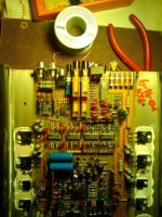
So then I started just messing with the switches, and right when I barely touched the crossover switch, the sound dropped to 1/2 the output in the right channel. popped it open and checked with a meter, and the switch is bad.
I feel pretty stupid since I took out perfectly good rca connectors and put in these ugly gray ones (you can see them in the pic.) Now I don't know if I should keep them in or try to put back in the mangled remains of originals.
Anyway, I've boxed the faulty switch in red in the pic, anyone know where I can buy a replacement, it is 6-pin, and it seems like it is soldered to the 18-pin switch below it. Also any ideas advice on how to remove and replace it once I do get a replacement?
Well concerning the pc2150, I'm an idiot. I swear that pushing on the rca was the problem, so I swapped them out with some ugly ones I got at a spareparts store for 10 cents. Fired up the amp and had the same problem.
So then I started just messing with the switches, and right when I barely touched the crossover switch, the sound dropped to 1/2 the output in the right channel. popped it open and checked with a meter, and the switch is bad.
I feel pretty stupid since I took out perfectly good rca connectors and put in these ugly gray ones (you can see them in the pic.) Now I don't know if I should keep them in or try to put back in the mangled remains of originals.
Anyway, I've boxed the faulty switch in red in the pic, anyone know where I can buy a replacement, it is 6-pin, and it seems like it is soldered to the 18-pin switch below it. Also any ideas advice on how to remove and replace it once I do get a replacement?
Attachments
The two switches are one unit (unless someone has done some surgery on them). It's likely that the top switch makes/breaks the contacts on the front 6 terminals. The bottom switch makes/breaks the contact on the rear 12 terminals.
Try cleaning them. There are openings in the clear covers that will allow you to spray contact cleaner into the switch. Make sure the contact cleaner is safe for plastics.
If the gray jacks are in good condition (no corrosion), they will work as well as the originals.
Try cleaning them. There are openings in the clear covers that will allow you to spray contact cleaner into the switch. Make sure the contact cleaner is safe for plastics.
If the gray jacks are in good condition (no corrosion), they will work as well as the originals.
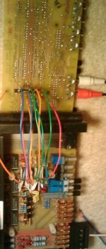
Okay, so inorder to figure out the connector I made some jumper wires.
I unplugged each of the wires for RF,LF,RR,LR and still had the low pass signal on pin 2. When I unplugged pin 1, the signal on pin2 dissappeared, so I'm pretty certain now that pin 1 carries the signal to the bottom board for lp filter conditioning.
The weird part is that I can't see the signal on pin 1 with my multimeter. For example, with and input of 100 hz at 0.5 Vrms AC, When set to AC Voltage, I can see about 0.3 Vrms on my multimeter on pin 2. When set to Hz, I can see 100hz on pin 2 as well. But when I measure voltage or freq on pin 1, I see nothing. Yet if I disconnect pin 1, then the signal disappears from pin 2.
could it be possible that pin 1 has a different ground point than all the other signals in connector and thats why my meter doesn't see anything on it?
The other issue I noticed is that if I use the front inputs with the combine switch activated and the rears are set to lp, .5 Vrms input translates to .5 Vrms on pin 2. But when using the rear inputs with the rear channels set to lp, .5 Vrms translates to only about .25 Vrms on pin 2.
Attachments
- Status
- This old topic is closed. If you want to reopen this topic, contact a moderator using the "Report Post" button.
- Home
- General Interest
- Car Audio
- PPI 4100 front input leaking to rear ouput