Well, I don't know what to say. It works beautifully. If I remove the feedback, it spikes to over 24V when minimally loaded. Respectfully, I refer you to App notes on Linear's LT3782, 2-F Step-up Converter driver chip. (Not the chip I used. I used the SG3525, though the principle is the same)
Not wanting to argue here, but this is what I have experienced.
Not wanting to argue here, but this is what I have experienced.
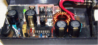
Interesting, I'll have to look at that. I'm not doubting the performance of your circuit either. Even if it isn't/wasn't a flyback it still is able to do what you want it to do.  Your boards look very nice! Am I correct that it is wound like a push-pull transformer primary would be?
I'd expect the opposite MOSFET to clamp the output - but the leakage inductance lessens this of course. How much load can it take above 24V?
I'd expect the opposite MOSFET to clamp the output - but the leakage inductance lessens this of course. How much load can it take above 24V?
No big deal. I know the "lost-in-translation" thing can be a PITA (Pain In The A$$) sometimes.
As for the windings, yes, you are correct in understanding that it is wound like the primary side of a transformer. And, I must say that I chose my words poorly: The other half of the MBR2545CT doesn't clamp the spike, the other MOSFETs source does. The spike is limited to 19.5V by the feedback section of the '3525. As for loads above 24V, I don't know- I've never tried it. Good idea to do sometime.
Another Application note to look at is the Unitrode division of Texas Instruments, UCC3806. This is the BiCMOS version of the 1846/2846/3846 family of current-mode PWM chips. Last diagram shows the "autoformer" topology being substituted for the true transformer where isolation is not necessary.
luka said:Hi Steve
Nice work as always, PCB looks like DIY, without silk and solder mask, I always like plated holes, makes life more easy. Is that heatsink big enough? Will you take one more pic when finnished? Maybe take output ripple at full output? Anyway look great and I hope it works that way to
Thanks, Luka. Tried first unit last night, promptly blew a 10A Fast-blow fuse when I plugged it in. Probably a bad solder-job. I have crappy Radio Shack soldering irons- I guess ya' get what ya' pay for. Just borrowed one of the technicians' Weller soldering stations that goes up to 830 Fahrenheit or 443 Centigrade. This should work much better. Will report tomorrow on results.
If I can translate Fluke readouts to screen, I will post waveforms.
Is it this appnote?
http://focus.ti.com/lit/an/slua150/slua150.pdf
If you look at the schematic of the autoformer topology it does have an output inductor like a regular forward converter. When switches are off diode cathode node is at Vin. When a switch is on the node will sit at 2*Vin.
If you remove the inductor from this topology it will be like those SMPS often used for car audio - no output inductor but still some regulation is possible as long as one doesn't try to go too low down in voltage thanks to the leakage inductance. I'm pretty sure you could get better performance by substituting the inductor you have with a ferrite core transformer as I'm pretty sure most energy is delivered directly during the forward cycle right now and very little by flyback action. Adding an output inductor after output rectifier on top of that might give even better performance. (But one more component)
I guess ya' get what ya' pay for
Please do.If I can translate Fluke readouts to screen, I will post waveforms.
It's never too late when it comes to correct the wrong circuit topology...
I suspect there is not such a thing as a buck, boost or flyback converter with a single inductor, two windings having opposite polarities and two "push-pull" switches. It's probably relying on the small (air) leakage inductance for working, rather than on main (core) inductance as expected.
I suspect there is not such a thing as a buck, boost or flyback converter with a single inductor, two windings having opposite polarities and two "push-pull" switches. It's probably relying on the small (air) leakage inductance for working, rather than on main (core) inductance as expected.
Talking about SMPS used in car audio, they usually put quite big capacitor bank for secondaries, without any inductor.If you remove the inductor from this topology it will be like those SMPS often used for car audio - no output inductor but still some regulation is possible as long as one doesn't try to go too low down in voltage thanks to the leakage inductance. I'm pretty sure you could get better performance by substituting the inductor you have with a ferrite core transformer as I'm pretty sure most energy is delivered directly during the forward cycle right now and very little by flyback action. Adding an output inductor after output rectifier on top of that might give even better performance. (But one more component)
Is putting big cap bank (without L) in secondary has the same effect with LC (where C is small compared to the first case)?
Eva said:It's never too late when it comes to correct the wrong circuit topology...
I suspect there is not such a thing as a buck, boost or flyback converter with a single inductor, two windings having opposite polarities and two "push-pull" switches. It's probably relying on the small (air) leakage inductance for working, rather than on main (core) inductance as expected.
I meant the six boards already produced. As for changing the output section, I could remove the 2200mF cap before the inductor and see what happens, but I want to take waveform pics (timing cap, gate drive, output ripple, etc.) from hi-power test, as is, first. Found a design flaw and corrected it: (+) & (-) EA input connections reversed. Couldn't achieve regualtion. Now works great at 19.90V with minimal (25mA) load.
I have to seal this one up & deliver it because it's for someone else, but I'm nearing completion on unit #2 (for me). Mine will have a BLUE LED, making it real cool! I will take waveform pics with, & w/o 2200mF cap.
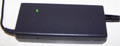
Here are a couple of pics of the just-finished unit working
Attachments
12v=19v 4,7A dcdc files new links --> www.320volt.com 
audio electronic --> www.tamircihasan.forumup.com www.subwoofer.forumup.com wwww.diyot.tr.gg

audio electronic --> www.tamircihasan.forumup.com www.subwoofer.forumup.com wwww.diyot.tr.gg
I'm about to build the same sort of project for the same application, running/charging a laptop in a car. I'm making a couple of changes (using an output inductor, and doing the thing mainly SMT) but that's about it.
But before I build something that blows up in my face... is flux walking of the transformer something I should worry about? I'm debating whether to keep the voltage-mode SG3525 and rely on parasitics to balance the thing, or go with a current-mode controller like a UCC3808.
Thanks for the suggestions if you have any...
gmarsh,
Since I did not try this with either a UC1846 or UCC3806, I suppose it would work fine, though circuit complexity will go up a little bit due to the added current-sensing components. I have used the '1846 and the '3806 before, and have several samples on hand, but since most of the talk here is on the TL494, SG3525, and the MC33025, these are the chips I have concentrated on.
As for flux-wlking, see post #74, this thread. As opposite phase is energized, any flux remaining in the core is canceled out.
I DID do a car amplifier SMPS about 15 years back, and it worked beautifully, easily supplying two channels of over 90W onto 4ohms, and putting almost no noise into the signal path, despite its proximity to the main amp board.
I have a few UCC3808s, but have not yet used 'em. Unfortunately, they are the SOIC package, and not the PDIP pkg. I DO like the chip, though. Complete current-mode controller with capabilities of its 16-pin big brothers, all in an 8-Pin DIP pkg!
Hope this helps.
Steve
- Status
- This old topic is closed. If you want to reopen this topic, contact a moderator using the "Report Post" button.
- Home
- Amplifiers
- Power Supplies
- 12v=19v 4,7A dcdc

