Thanks Mark! You have given me some more to think about! I new zeners could be used to set a particular voltage but I've never looked at how they performed. Some more sims for me
Tony.
I find the circuit in post 10 intriguing since there aren't any output caps to worry about along with its stellar performance.
Can D3 be changed to a 12V Zener in order to get 12V output, or would I need to change R3 and R4 also?
Can someone answer this question??
Hi Ammel, the zenner just sets the reference voltage, it is the combination of the resistive divider that sets the final output voltage.
The circuit as shown would actually give you 12.4V out.
from this formula that Mark posted.
VOUT = 6.2V * (R3 + R4) / R4
VOUT = 6.2 * (330 + 330) / 330 = 6.2 * 660 / 330 = 6.2 * 2 = 12.4V
If you were to use a potentiometer for one of the resistors you could adjust according to the voltage you need.
edit: Using R3 = 316 and R4 = 332 (E96 values) will get you around 12.1 V
Tony.
Last edited:
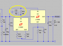
I think you may be pleasantly surprised if you replace R14 (200 ohms) with a parallel combination of 47Kohms and 68 microhenries. It's only one extra component.
LTSPICE includes a factory-supplied simulation model of a through-hole 68uH inductor, manufactured by Wurth. It is in stock and ready to ship from DigiKey (I checked) and probably many other distributors (I didn't check).
_
LTSPICE includes a factory-supplied simulation model of a through-hole 68uH inductor, manufactured by Wurth. It is in stock and ready to ship from DigiKey (I checked) and probably many other distributors (I didn't check).
_
Attachments
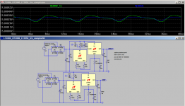
Hi Mark, I tried it out but I might be missing something.... It actually increased the magnitude of the ripple and made it closer to a triangle wave... as compared to just the cap and resistor.
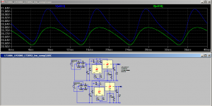
Below is comparison of 200 ohms with 10uF (green curve) and 47k 10uF with 68mH parallel blue trace.
I also tried 68uH but it was more saw tooth like...
Is this more for real world? filtering out high frequency stuff from the supply to the LT3092?
Tony.
Below is comparison of 200 ohms with 10uF (green curve) and 47k 10uF with 68mH parallel blue trace.
I also tried 68uH but it was more saw tooth like...
Is this more for real world? filtering out high frequency stuff from the supply to the LT3092?
Tony.
Attachments
How many of your readers know what "V(n003)" means? I don't.
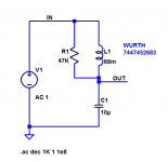
Maybe the 68 mH really does make things worse. The way to find out is to attach node names to the SET pins of the final output regulators, LT3080s. Then plot the SET pin voltage with 200R and again with 68mH//47K. Its purpose is to turbocharge the LT3092 current source, so you get a stiffer current into the 15K set resistor, so you get less ripple on the SET pin. But maybe the inductor actually makes things worse instead of better.
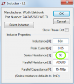
The very very low frequency response is set by the inductor's DC resistance and the 10uF capacitance. Since the DC resistance is 90 ohms in the Wurth-supplied model (you are using the Wurth supplied model?), you could install another 110 ohm resistor in series, to match the VVLF response of the 200 ohm resistor original. But that 110R does add yet another component, albeit a cheap one.
_
Maybe the 68 mH really does make things worse. The way to find out is to attach node names to the SET pins of the final output regulators, LT3080s. Then plot the SET pin voltage with 200R and again with 68mH//47K. Its purpose is to turbocharge the LT3092 current source, so you get a stiffer current into the 15K set resistor, so you get less ripple on the SET pin. But maybe the inductor actually makes things worse instead of better.
The very very low frequency response is set by the inductor's DC resistance and the 10uF capacitance. Since the DC resistance is 90 ohms in the Wurth-supplied model (you are using the Wurth supplied model?), you could install another 110 ohm resistor in series, to match the VVLF response of the 200 ohm resistor original. But that 110R does add yet another component, albeit a cheap one.
_
Attachments
Sorry I should have said that the measurements were taken at the junction between the LT3092 IN pin and the bottom of the 47K resistor. I didn't check for effect on the SET pin of the LT3080. I think I did have a look at the current flowing through the 15K resistor but that was early on before I set up two almost identical circuits for comparison.
Thanks for the explanation, I was missing something! I was assuming it was to reduce the ripple even more on the input to the LT3092, I didn't realize it was actually to improve it's output. I will take another look! As I said at the begining (I think) My electronics knowledge is not great, but I do like to experiment. Anything like this is greatly appreciated!
edit: and yes I did use the wurth model with the 90 ohms series resistance (same part number you showed in the sceenshot).
Tony.
Last edited:
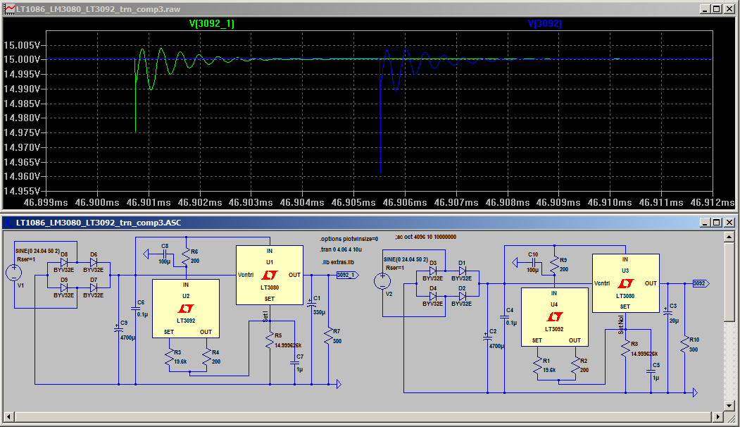
It's taken a while to do this but I wanted to test not just the ripple but the transient response. I created a simple 555 square wave generator (from a web schematic I found somewhere). I made two identical circuits and added the 68mH inductor on one of them.
What I found was that the inductor pretty much has no effect on the transient response. I modified the original to have only 20uF on the output and 20pf on the set pin, to try and get what would be the worst scenario from a transient response POV.
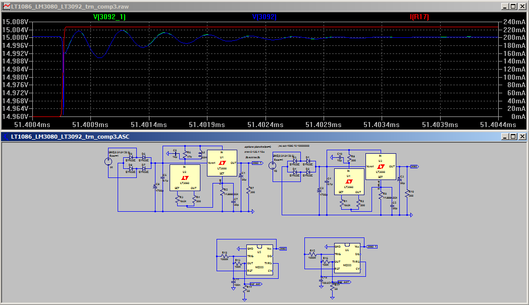
The above shows the rising response.
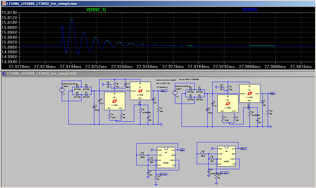
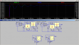
and this one the falling. In each case the _1 version is with the inductor added, not that you can really see any difference")
I only thought to put the square wave current in for the rising one. I didn't go back and redo the falling one because I didn't write down the cap values I needed to get the pulses overlapping (and it took a long time to tune it in!)
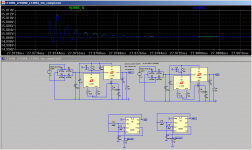
I also measured ripple and in that case I thought with the inductor was slightly worse, but on revisiting it appears that there is really no difference.
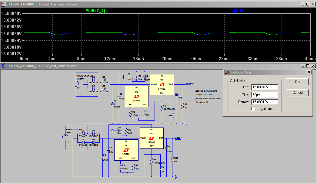
ripple with 1uF set pin.
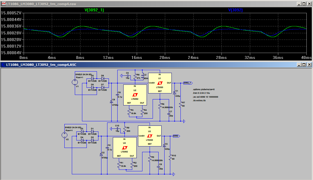
with a 20p set pin resistor I can now see where I thought the ripple was slightly worse.
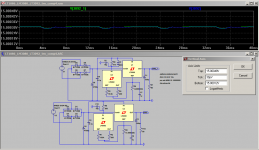
Just for fun as couple of extra transient response measurements.

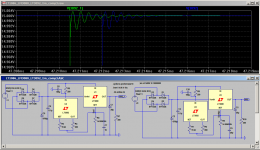
This one shows the difference (or lack there of) of 1uF on the set pin (green) compared to 20p on the set pin (blue). I think the datasheet stated that a bigger cap on the set pin would improve transient response.... certainly when beefing up the current with the LT3092 it doesn't seem to be the case..
As a sanity check the above shows the difference between a 330uF cap on the output (green) and a 20uF cap on the output (blue). You can definitely see with this one that the bigger cap is improving the transient response (albeit with a very slightly slower recovery time.. it is only around 4uS).
So my conclusion at this point is that the inductor is not really helping or hindering with the tests I've done in the simulator. The set pin cap doesn't seem to make much difference to transient response if using the LT3092, and the output cap does make a difference to transient response of the reg (admittedly a 240mA square wave is a pretty harsh test and it seems to cope with it prettywell).
Tony.
What I found was that the inductor pretty much has no effect on the transient response. I modified the original to have only 20uF on the output and 20pf on the set pin, to try and get what would be the worst scenario from a transient response POV.
The above shows the rising response.
and this one the falling. In each case the _1 version is with the inductor added, not that you can really see any difference
I only thought to put the square wave current in for the rising one. I didn't go back and redo the falling one because I didn't write down the cap values I needed to get the pulses overlapping (and it took a long time to tune it in!)
I also measured ripple and in that case I thought with the inductor was slightly worse, but on revisiting it appears that there is really no difference.
ripple with 1uF set pin.
with a 20p set pin resistor I can now see where I thought the ripple was slightly worse.
Just for fun as couple of extra transient response measurements.
This one shows the difference (or lack there of) of 1uF on the set pin (green) compared to 20p on the set pin (blue). I think the datasheet stated that a bigger cap on the set pin would improve transient response.... certainly when beefing up the current with the LT3092 it doesn't seem to be the case..
As a sanity check the above shows the difference between a 330uF cap on the output (green) and a 20uF cap on the output (blue). You can definitely see with this one that the bigger cap is improving the transient response (albeit with a very slightly slower recovery time.. it is only around 4uS).
So my conclusion at this point is that the inductor is not really helping or hindering with the tests I've done in the simulator. The set pin cap doesn't seem to make much difference to transient response if using the LT3092, and the output cap does make a difference to transient response of the reg (admittedly a 240mA square wave is a pretty harsh test and it seems to cope with it prettywell).
Tony.
Attachments
-
 transient_comparison_rising.png31.6 KB · Views: 451
 -
 transient_comparison_falling.png30.9 KB · Views: 456
 -
 inductor_comparison_ripple.png33.3 KB · Views: 450
 -
 inductor_comparison_ripple_20p.png32.2 KB · Views: 458
 -
 Set_pin_transient_comp.png35.3 KB · Views: 443
 -
 out_cap_transient_comp.png35.2 KB · Views: 460
- Status
- This old topic is closed. If you want to reopen this topic, contact a moderator using the "Report Post" button.
- Home
- Amplifiers
- Power Supplies
- From LM317 to LT3080 an LTSpice Journey