1st a disclaimer. I have only a basic knowledge of electronics and like to experiment. What you see in this thread is some of the results of that. At this stage they are only sims, if and when I build an actual circuit I won’t actually have the capability to measure the output impedance to verify that the sims match reality so keep that in mind.
Additionally when putting in the title for this new thread the forum suggested I should look at this thread http://www.diyaudio.com/forums/power-supplies/209727-linears-lt3080-regulator.html and looking at that lead to this one http://www.diyaudio.com/forums/tubes-valves/209067-21st-century-maida-regulator-2.html#post2961289 So it seems this has already been done at a much greater level (by people with infinitely more expertise than I have), but as I have spent quite a bit of time putting this together I’m going to post it anyway") It may be helpful to some less experienced people like myself. One thing that bugs me a little is that I’m not seeing the “highish” 60 mohm output impedance's mentioned in those threads… But enough of the disclaimer and on to the journey!
It may be helpful to some less experienced people like myself. One thing that bugs me a little is that I’m not seeing the “highish” 60 mohm output impedance's mentioned in those threads… But enough of the disclaimer and on to the journey!
About seven years ago I decided I needed a regulated power supply for my new concept for an active crossover. In looking for design considerations I came across this thread by jbau http://www.diyaudio.com/forums/power-supplies/143539-another-look-lm317-lm337-regulators.html I cherry picked one idea from there, which was that symmetry between the +ve and –ve rails may be important (subjectively) and one possible solution was to use two positive regulators, rather than the usual positive and negative pair.
I did some searches for such designs using two positive regulators but could not find any. Knowing one basic truth, that I really didn’t know very much at all, and a healthy fear of releasing the magic blue smoke, I decided try and design my own using LTSpice.
The result was YARPS http://www.diyaudio.com/forums/blog...egulated-power-supply-updated-2012-01-02.html. It works, and has been in use for a number of years, but I now know it was a rather naïve design, and certainly not a pinnacle of engineering excellence.
The main problem was that I fixated on the idea that the most important thing for the regulator to do was to reduce the ripple to a minute level. In addition I took a brute force passive approach to do this (large CRCRC pre reg). It wasn’t until I actually built the regulator that reality sunk in. The noise output of the LM317 I used (on breadboard) was around 1mV p2p! There wasn’t much point getting the ripple down to 2uV when the noise was greater by more than two orders of magnitude! :rolleys:
Recently jbau’s thread popped up again, and I read it with a bit more understanding than what I had first time around. This time, I Iatched onto the “flat impedance and phase throughout the audio band” idea.
I was curious about his statements that the LM317 was not suitable for audio. I started to sim with the LT1086 regulator and doing comparisons against the LM317, and by his definition of what was suitable the sims seemed to agree with his actual measurements. The first of those sim’s is here http://www.diyaudio.com/forums/powe...ok-lm317-lm337-regulators-13.html#post5114180
I’ve seen in a number of threads, people asking “why even bother with ancient reg’s such at the LM317 or LT1085 at all”, so I started to look at other alternatives and decided that the LT3080 seemed an interesting candidate. The first sim I did was in the most basic configuration. My own application calls for +- 10V output, so I did just a positive implementation using the single resistor (1Mohm) configuration. It looked pretty good! I also tried adding a small series resistance like jbau did and found that flattened the phase as well.
OK so enough with the waffle and on to the SIMS! (bet you thought I was never going to get there )
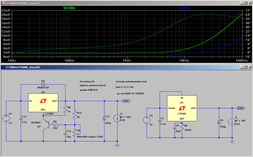
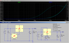
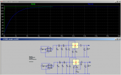
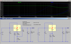
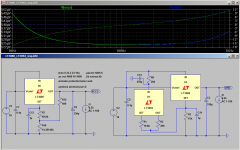
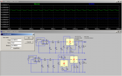
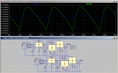
The first Sim below is a comparison of the output impedance of an LT1086 and the LT3080. This is without any added output resistance and configured for the more common 15V. Current draw is 250mA (which is what my circuit draws). Note that the transistor in the LT1086 circuit is the Fred Diekman mod, originally intended for the LM317. Also at this stage I didn’t actually have the 20p set pin bypass which shows in the sim. Note that the forum software seems to be resizing the inline images even when there is enough screen realestate to show them full size. Just click on the inline images and they should pop up to the native resolution which should display fine on most modern laptops or monitors (it is around 1048 x 653)
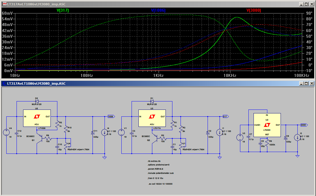
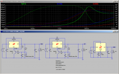
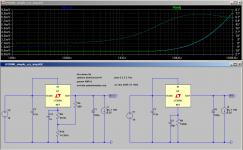
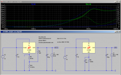
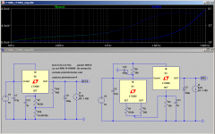
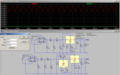
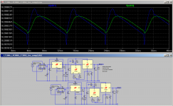
The second and third SIMs include an LT317A for comparison. Due to some weirdness in LTSpice I had to drop the current down to 150mA. With the addition of the LT317A the LT3080 sim’s low frequency impedance jumped up to around 2V!!! I assume that this is a strange bug in LTSpice as nothing else changed (just the addition of a separate LT317 circuit). The trend with the output impedance is quite obvious…. The LT317A shows the classic resonance that you get with a big cap with low ESR (esr of all output caps was set at 0.04 ohms).
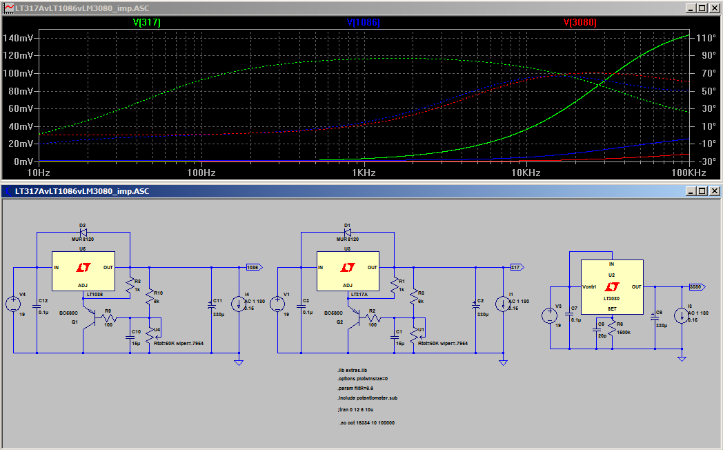
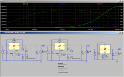
The third Sim is same as the second but with 0.2 ohms ESR for the LT317A output cap. This clearly shows that the extra series resistance damps out the resonance present in the second sim.
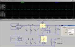
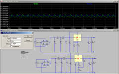
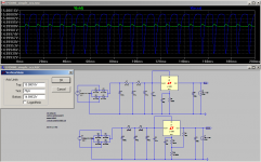
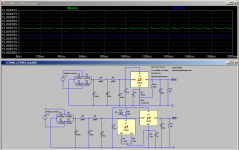
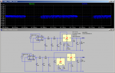
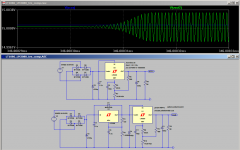
Time to move on to a transient analysis to have a look at ripple rejection. I used a similar CRCRC network to what I did on the YARPS supply but with reduced cap and resistor values. I decided to leave out the LM317 for this comparison. The Green trace is the LT1086 and Blue is the LT3080 the ticks are 30uV.
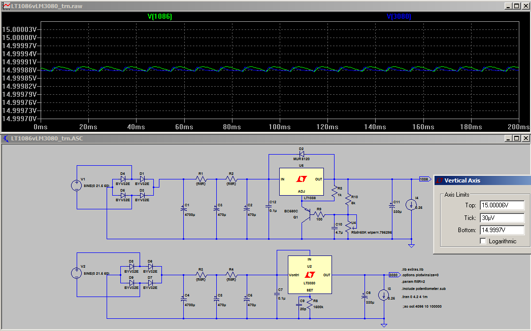
As you can see there is not much in it as far as the ripple reduction is concerned. The LT3080 does change the shape of the ripple compared to the LT1086 but magnitude reduction is similar. Both would be completely below the respective noise levels of the regulators. I'm not 100% sure of the real world noise output magnitude. the LT3080 shows a picture with 1V output with noise a bit over 100uV p2p I assume that this doesn't go up in direct proportion to output voltage Lt1086 is ~ 0.003% of output voltage..
After reading a bit more in the datasheet, there were some potential shortcomings with the single resistor configuration.
1. The output current of 10uA on the set pin is very small, and the potential for interference is quite high.
2. If you wanted to be able to adjust the output voltage, very large value pots would be required, eg a 100K pot would give you +- 0.5V of adjustment.
The datasheet gives a few ideas how this can be mitigated, one of which is to use a ccs to increase current at the set pin to 1mA. A passive option is shown. Another more vague comment is that the pin can be actively driven.
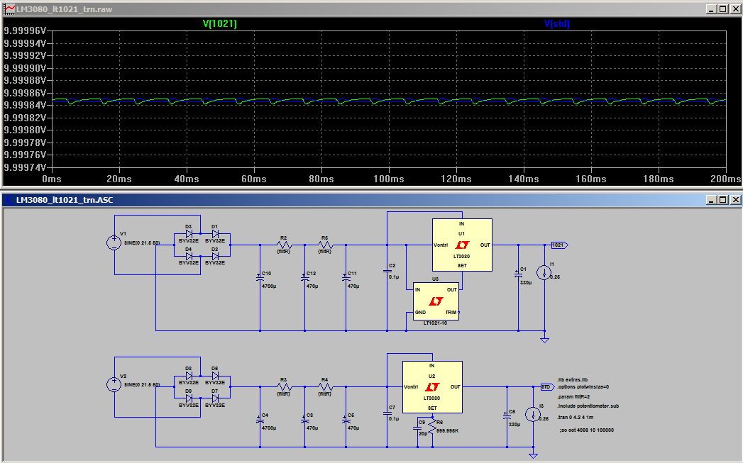
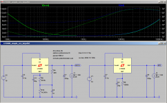
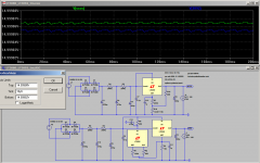
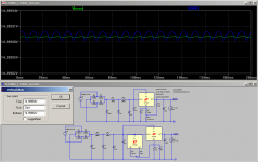
At this point I thought hmmm I wonder if I can use a precision voltage reference to drive the set pin. I simply tried putting a voltage set to 10V directly on the set pin and sure enough it worked. I then tried using an LT1021-10 10V reference and it worked. There is a very slight difference in output impedance compared to the resistor version, and interestingly the output ripple appears to be slightly higher than with the single resistor. After a while though I decided that this was not very flexible, especially since precision voltage references only come in a few values, the maximum seemingly being 10V. Both sims shown below:

That's enough for post number one. In the next post I look at using the simple ccs shown in the datasheet.
Additionally when putting in the title for this new thread the forum suggested I should look at this thread http://www.diyaudio.com/forums/power-supplies/209727-linears-lt3080-regulator.html and looking at that lead to this one http://www.diyaudio.com/forums/tubes-valves/209067-21st-century-maida-regulator-2.html#post2961289 So it seems this has already been done at a much greater level (by people with infinitely more expertise than I have), but as I have spent quite a bit of time putting this together I’m going to post it anyway
It may be helpful to some less experienced people like myself. One thing that bugs me a little is that I’m not seeing the “highish” 60 mohm output impedance's mentioned in those threads… But enough of the disclaimer and on to the journey! About seven years ago I decided I needed a regulated power supply for my new concept for an active crossover. In looking for design considerations I came across this thread by jbau http://www.diyaudio.com/forums/power-supplies/143539-another-look-lm317-lm337-regulators.html I cherry picked one idea from there, which was that symmetry between the +ve and –ve rails may be important (subjectively) and one possible solution was to use two positive regulators, rather than the usual positive and negative pair.
I did some searches for such designs using two positive regulators but could not find any. Knowing one basic truth, that I really didn’t know very much at all, and a healthy fear of releasing the magic blue smoke, I decided try and design my own using LTSpice.
The result was YARPS http://www.diyaudio.com/forums/blog...egulated-power-supply-updated-2012-01-02.html. It works, and has been in use for a number of years, but I now know it was a rather naïve design, and certainly not a pinnacle of engineering excellence
. The main problem was that I fixated on the idea that the most important thing for the regulator to do was to reduce the ripple to a minute level. In addition I took a brute force passive approach to do this (large CRCRC pre reg). It wasn’t until I actually built the regulator that reality sunk in. The noise output of the LM317 I used (on breadboard) was around 1mV p2p! There wasn’t much point getting the ripple down to 2uV when the noise was greater by more than two orders of magnitude! :rolleys:
Recently jbau’s thread popped up again, and I read it with a bit more understanding than what I had first time around. This time, I Iatched onto the “flat impedance and phase throughout the audio band” idea.
I was curious about his statements that the LM317 was not suitable for audio. I started to sim with the LT1086 regulator and doing comparisons against the LM317, and by his definition of what was suitable the sims seemed to agree with his actual measurements. The first of those sim’s is here http://www.diyaudio.com/forums/powe...ok-lm317-lm337-regulators-13.html#post5114180
I’ve seen in a number of threads, people asking “why even bother with ancient reg’s such at the LM317 or LT1085 at all”, so I started to look at other alternatives and decided that the LT3080 seemed an interesting candidate. The first sim I did was in the most basic configuration. My own application calls for +- 10V output, so I did just a positive implementation using the single resistor (1Mohm) configuration. It looked pretty good! I also tried adding a small series resistance like jbau did and found that flattened the phase as well.
OK so enough with the waffle and on to the SIMS! (bet you thought I was never going to get there
) The first Sim below is a comparison of the output impedance of an LT1086 and the LT3080. This is without any added output resistance and configured for the more common 15V. Current draw is 250mA (which is what my circuit draws). Note that the transistor in the LT1086 circuit is the Fred Diekman mod, originally intended for the LM317. Also at this stage I didn’t actually have the 20p set pin bypass which shows in the sim. Note that the forum software seems to be resizing the inline images even when there is enough screen realestate to show them full size. Just click on the inline images and they should pop up to the native resolution which should display fine on most modern laptops or monitors (it is around 1048 x 653)
The second and third SIMs include an LT317A for comparison. Due to some weirdness in LTSpice I had to drop the current down to 150mA. With the addition of the LT317A the LT3080 sim’s low frequency impedance jumped up to around 2V!!! I assume that this is a strange bug in LTSpice as nothing else changed (just the addition of a separate LT317 circuit). The trend with the output impedance is quite obvious…. The LT317A shows the classic resonance that you get with a big cap with low ESR (esr of all output caps was set at 0.04 ohms).
The third Sim is same as the second but with 0.2 ohms ESR for the LT317A output cap. This clearly shows that the extra series resistance damps out the resonance present in the second sim.
Time to move on to a transient analysis to have a look at ripple rejection. I used a similar CRCRC network to what I did on the YARPS supply but with reduced cap and resistor values. I decided to leave out the LM317 for this comparison. The Green trace is the LT1086 and Blue is the LT3080 the ticks are 30uV.
As you can see there is not much in it as far as the ripple reduction is concerned. The LT3080 does change the shape of the ripple compared to the LT1086 but magnitude reduction is similar. Both would be completely below the respective noise levels of the regulators. I'm not 100% sure of the real world noise output magnitude. the LT3080 shows a picture with 1V output with noise a bit over 100uV p2p I assume that this doesn't go up in direct proportion to output voltage
Lt1086 is ~ 0.003% of output voltage.. After reading a bit more in the datasheet, there were some potential shortcomings with the single resistor configuration.
1. The output current of 10uA on the set pin is very small, and the potential for interference is quite high.
2. If you wanted to be able to adjust the output voltage, very large value pots would be required, eg a 100K pot would give you +- 0.5V of adjustment.
The datasheet gives a few ideas how this can be mitigated, one of which is to use a ccs to increase current at the set pin to 1mA. A passive option is shown. Another more vague comment is that the pin can be actively driven.
At this point I thought hmmm I wonder if I can use a precision voltage reference to drive the set pin. I simply tried putting a voltage set to 10V directly on the set pin and sure enough it worked. I then tried using an LT1021-10 10V reference and it worked. There is a very slight difference in output impedance compared to the resistor version, and interestingly the output ripple appears to be slightly higher than with the single resistor. After a while though I decided that this was not very flexible, especially since precision voltage references only come in a few values, the maximum seemingly being 10V. Both sims shown below:
That's enough for post number one. In the next post I look at using the simple ccs shown in the datasheet.
Attachments
-
 LT1086vLT3080.png30.2 KB · Views: 2,400
 -
 simple_ccs_trn_1u.png29.6 KB · Views: 1,871
 -
 lt3080_LT1021_trn.png27.3 KB · Views: 2,010
 -
 LT3080_LT1021_imp.png29.9 KB · Views: 2,070
 -
 LT1086vLT3080_ripple.png32.2 KB · Views: 2,166
 -
 LT317AvLT1086vLT3080_damped.png30.1 KB · Views: 2,121
 -
 LT317AvLT1086vLT3080.png32 KB · Views: 2,184
Last edited:
Part 2.
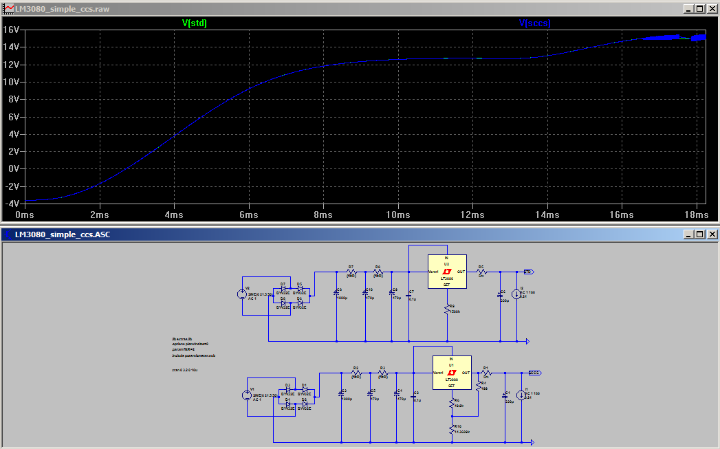
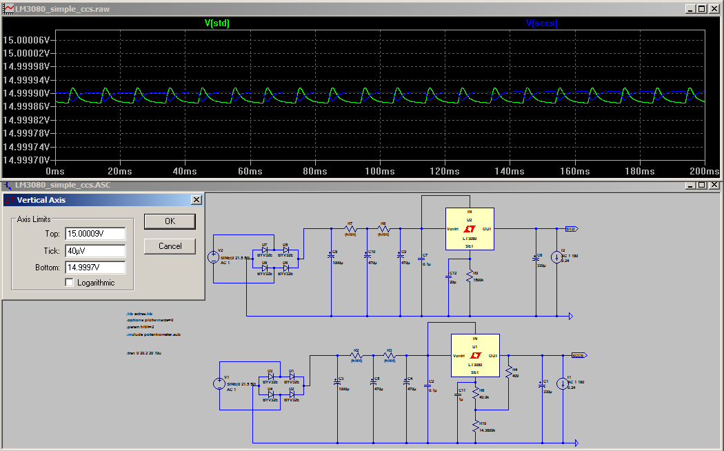
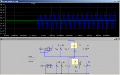
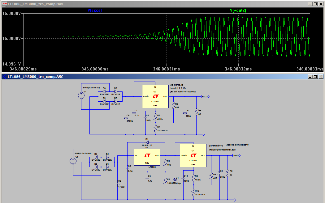
So the next strategy was to try the simple passive ccs presented in the datasheet. For whatever reason I did the transient analysis first and didn’t look at the output impedance, had I done it the other way around I may have never pursued the active ccs option, but that comes later... The first attempt was before I had put any 20pf caps on the set pin. I wondered why my transient analysis was getting stuck at a very early stage. I changed it to show data from time zero and what do you know, it was oscillating! The screen shot below shows that there is a problem.
Zooming in shows without doubt there is an oscillation!
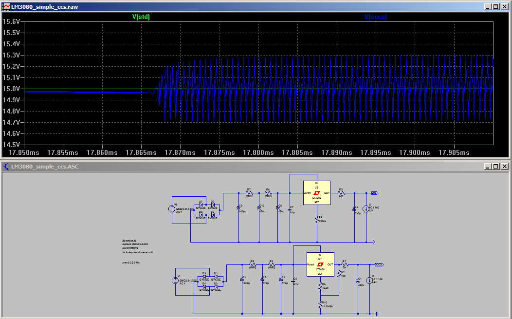
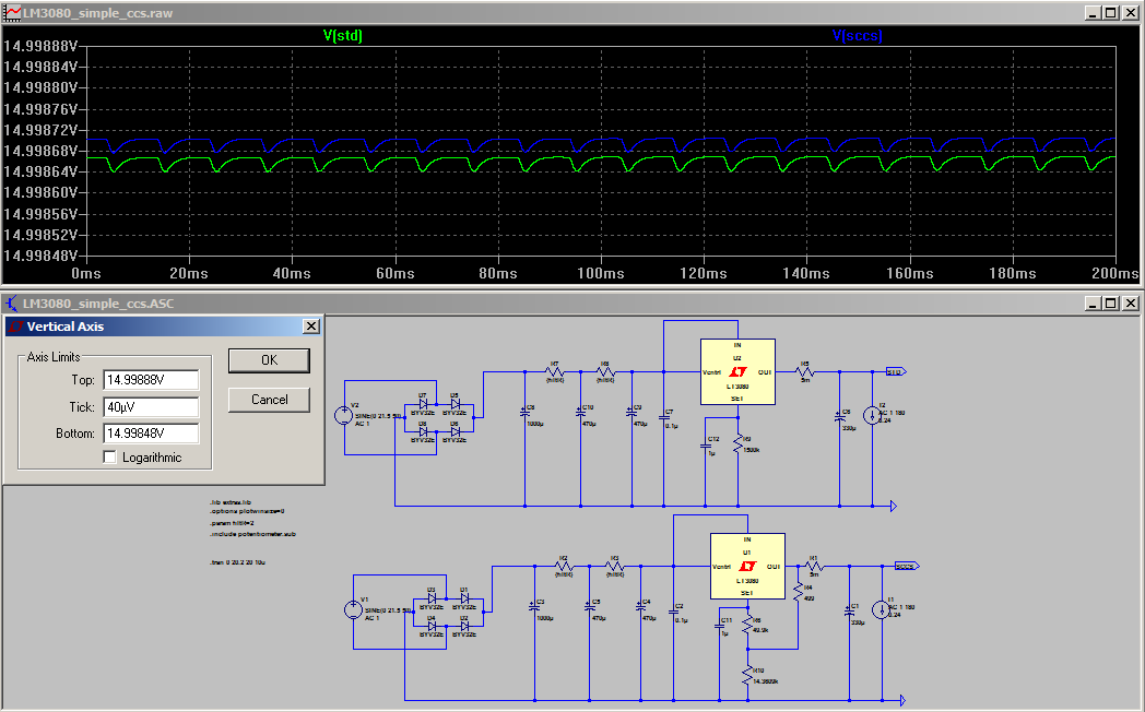
At this point I remembered the comment in the datasheet about 10-20pf on the set pin sometimes being necessary for stability. I added it and the oscillation stopped, but the ripple on the output was significantly worse with the simple ccs. I didn’t think about how I might go about fixing this passively at this point and started to look at active CCS options. Below is a screenshot showing the degradation I saw in ripple and why I initially naively just discounted this simple ccs as being unsuitable.
This led me to the next configuration which was using an LT3092 as a CCS. But I will go into that in the third post. I actually found out later some solutions to my issues with the passive ccs one of which I will detail now.
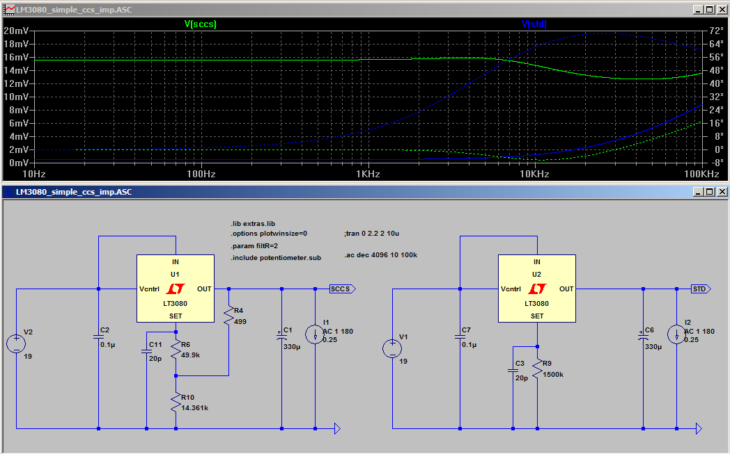
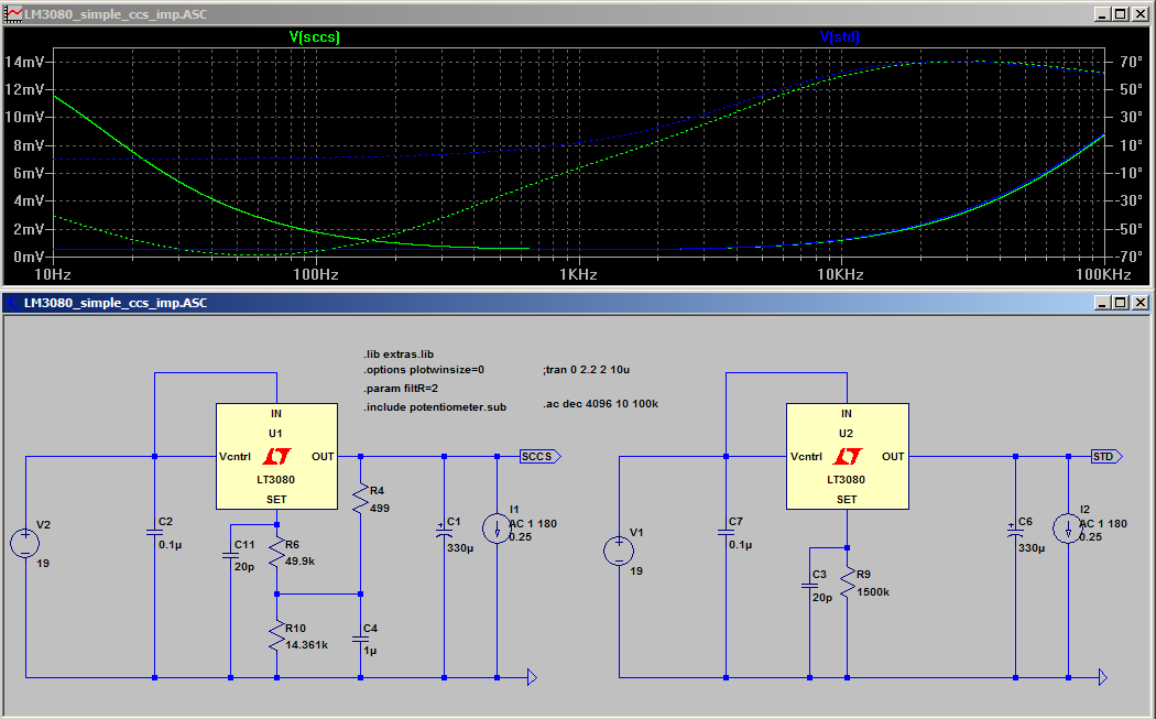
When doing the output impedance sim on the passive ccs something interesting becomes apparent. With no cap on the set pin pin the output impedance is significantly higher, and there appears to be a small resonance!
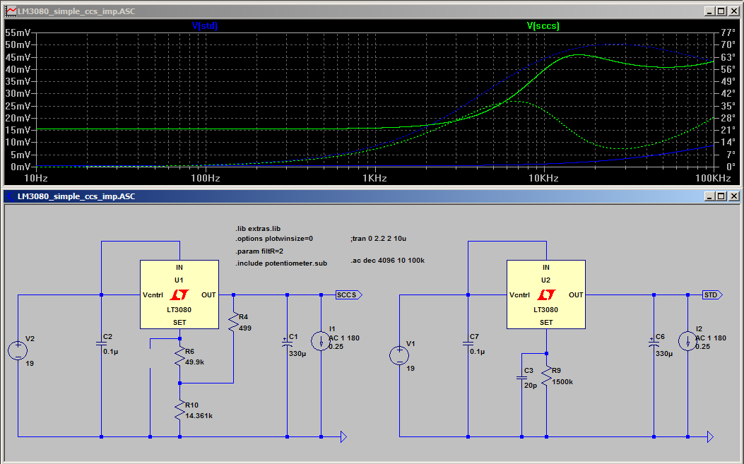
With 20p present, the resonance is pretty much gone, but the output impedance is still significantly higher.
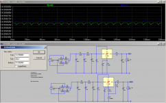
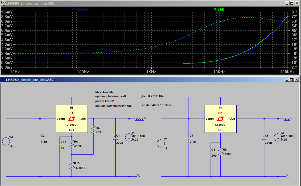
Increasing the set pin cap to 1uF (max recommended in the datasheet) brings the output impedance back to similar to the single resistor configuration, at the expense of a very long startup time (approx. 20 seconds to get to full output voltage).
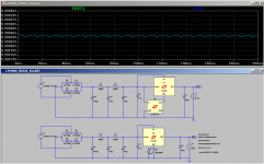
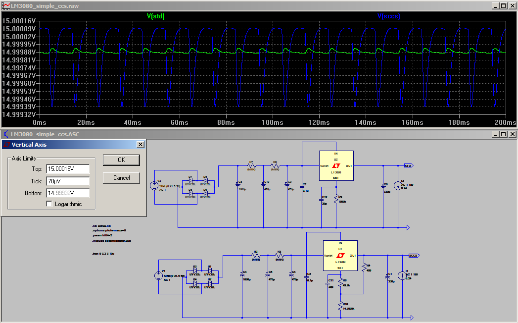
Revisiting the transient analysis with the 1uF cap on the set pin we now find that our ripple problem has gone away!
Note that when 1uF is put on the set pin with the single resistor config the output ripple is very similar between the single resistor config and the simple ccs.
I also tried an alternate configuration with 1uF from the 499 resistor to ground but this had a rising output impedance below 1Khz, as below.
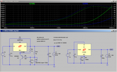
Final sim for this post shows the timing difference for voltage ramp up between the single resistor and ccs with 1uF on the set pin.
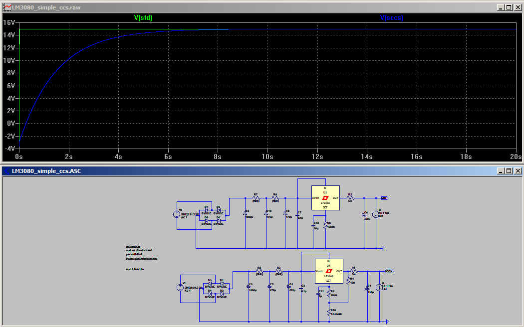
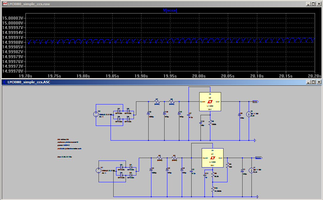
For all intents and purposes the target output voltage has been reached by about 8 seconds, however it is still apparent that the voltage has not completely stabilized even at 20 seconds as shown below (though the minute difference is pretty much academic).
The next post will have details of using the LT3092 as a CCS, but I have to prepare the sim screen shots so it might be a little while. I'll put in placeholder posts for the third and fourth parts.
So the next strategy was to try the simple passive ccs presented in the datasheet. For whatever reason I did the transient analysis first and didn’t look at the output impedance, had I done it the other way around I may have never pursued the active ccs option, but that comes later... The first attempt was before I had put any 20pf caps on the set pin. I wondered why my transient analysis was getting stuck at a very early stage. I changed it to show data from time zero and what do you know, it was oscillating! The screen shot below shows that there is a problem.
Zooming in shows without doubt there is an oscillation!
At this point I remembered the comment in the datasheet about 10-20pf on the set pin sometimes being necessary for stability. I added it and the oscillation stopped, but the ripple on the output was significantly worse with the simple ccs. I didn’t think about how I might go about fixing this passively at this point and started to look at active CCS options. Below is a screenshot showing the degradation I saw in ripple and why I initially naively just discounted this simple ccs as being unsuitable.
This led me to the next configuration which was using an LT3092 as a CCS. But I will go into that in the third post. I actually found out later some solutions to my issues with the passive ccs one of which I will detail now.
When doing the output impedance sim on the passive ccs something interesting becomes apparent. With no cap on the set pin pin the output impedance is significantly higher, and there appears to be a small resonance!
With 20p present, the resonance is pretty much gone, but the output impedance is still significantly higher.
Increasing the set pin cap to 1uF (max recommended in the datasheet) brings the output impedance back to similar to the single resistor configuration, at the expense of a very long startup time (approx. 20 seconds to get to full output voltage).
Revisiting the transient analysis with the 1uF cap on the set pin we now find that our ripple problem has gone away!
Note that when 1uF is put on the set pin with the single resistor config the output ripple is very similar between the single resistor config and the simple ccs.
I also tried an alternate configuration with 1uF from the 499 resistor to ground but this had a rising output impedance below 1Khz, as below.
Final sim for this post shows the timing difference for voltage ramp up between the single resistor and ccs with 1uF on the set pin.
For all intents and purposes the target output voltage has been reached by about 8 seconds, however it is still apparent that the voltage has not completely stabilized even at 20 seconds as shown below (though the minute difference is pretty much academic).
The next post will have details of using the LT3092 as a CCS, but I have to prepare the sim screen shots so it might be a little while. I'll put in placeholder posts for the third and fourth parts.
Attachments
-
 simple_ccs_trn_1u_startup_zoom.png26.7 KB · Views: 1,821
 -
 simple_ccs_trn_1u_startup.png24.5 KB · Views: 1,838
 -
 simple_ccs_imp_20p_alt.png27.7 KB · Views: 1,854
 -
 simple_ccs_trn_1u_20p.png29.1 KB · Views: 1,862
 -
 simple_ccs_imp_1u.png27.5 KB · Views: 1,861
 -
 simple_ccs_imp_20p.png26.8 KB · Views: 1,887
 -
 simple_ccs_imp_nocap.png27.5 KB · Views: 1,868
 -
 simple_ccs_trn_20p.png32.1 KB · Views: 1,891
 -
 LT3080_simple_ccs_oscilation_zoom.png28.1 KB · Views: 1,938
 -
 LT3080_simple_ccs_oscilation.png24.5 KB · Views: 1,950
Part 3.
So as mentioned in part two I initially discounted the passive ccs shown in the datasheet and decided to try an active solution. I toyed with the idea of creating my own, but decided that there must be a simple solution available. Initially I was looking at the lm334 but I had some concerns about thermal stability. A bit of googling turned up the LT3092 http://cds.linear.com/docs/en/datasheet/3092fc.pdf.
The high precision and stable thermal performance seduced me. I started out with transient analysis and the simplest implementation. I was a bit concerned about the ripple from the unregulated supply so tried running it off the reg output. Bzzzt. Should have known I’d need a higher potential than the set pin voltage for it to work What actually happened was I ended up with about 150mV on the output!
Next I powered it straight off the last filter cap. Without the 20p on the set pin it oscillated.
I added the 20p and that fixed the problem, but the ripple was coming though in the current output and affecting the regs output ripple, which was much higher than for the simple ccs.
I thought "this CCS has very little current draw, I should be able to add another RC before it without much voltage drop". The next sim shows the ripple at the input to the reg compared to the input of the LM3092 with a 200 ohm resistor and 470uF cap added in. the voltage drop is minimal and an even higher value resistor could be used.
This had the following effect on the output ripple:
This is very similar to the simple ccs.
Finally I did a sim increasing the set pin to 1uF as per the simple ccs and the result of that is below:
I also started to wonder about the dropout voltage (I’d been doing all of the impedance sims with 4V in to out differential, and the voltages in the transient analysis were set up for my original 10V out (woops). I was sailing close to the wind! I tried upping the voltage, and started getting weird results with the simple ccs. -33.6V on the output. I’d seen something like this before and reducing the DC current on the load fixed it. As did changing from a current sink to load resistors.
I changed the current load to 60 ohm resistors and ran again. Voltage increased very slightly but ripple pretty much stays the same. Phew don’t have to do all of the sims in posts 1 and 2 again… But it does show that it is just as important to check your voltages in your sims as it is in the real world
So at this point there doesn't seem to be much advantage using the active ccs over the passive one. On to the impedance sim.
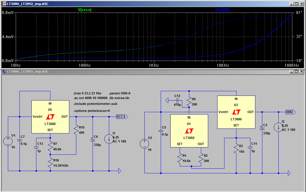
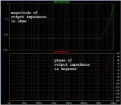
Now we do see a slight difference. The phase remains flat at zero degrees down to 10Hz with the LT3092 whereas with the simple CCS the phase starts to drop around 200Hz finishing at around -18deg at 10 Hz. If we zoom in we can see why this is happening:
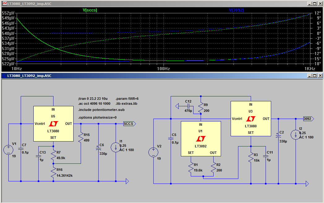
The impedance is rising (albeit a very small amount) below 100Hz in the simple ccs implementation. This is not a lot but if the phase is as important as what jbau thought in his LM317 thread, then this may be a worthwhile consideration, if you want the flattest possible phase (assuming the sim matches reality!!)
So at this point I’m undecided about the use of the LT3092. If you want to be a perfectionist and the additional cost isn’t a concern then why not, but based on the sim data alone, I would definitely lump it in the diminishing returns category. Of course it may make more of a difference in a real world implementation, especially if the output impedance is in reality much higher as mentioned in the posts linked in part 1.
So as mentioned in part two I initially discounted the passive ccs shown in the datasheet and decided to try an active solution. I toyed with the idea of creating my own, but decided that there must be a simple solution available. Initially I was looking at the lm334 but I had some concerns about thermal stability. A bit of googling turned up the LT3092 http://cds.linear.com/docs/en/datasheet/3092fc.pdf.
The high precision and stable thermal performance seduced me
. I started out with transient analysis and the simplest implementation. I was a bit concerned about the ripple from the unregulated supply so tried running it off the reg output. Bzzzt. Should have known I’d need a higher potential than the set pin voltage for it to work What actually happened was I ended up with about 150mV on the output! Next I powered it straight off the last filter cap. Without the 20p on the set pin it oscillated.
I added the 20p and that fixed the problem, but the ripple was coming though in the current output and affecting the regs output ripple, which was much higher than for the simple ccs.
I thought "this CCS has very little current draw, I should be able to add another RC before it without much voltage drop". The next sim shows the ripple at the input to the reg compared to the input of the LM3092 with a 200 ohm resistor and 470uF cap added in. the voltage drop is minimal and an even higher value resistor could be used.
This had the following effect on the output ripple:
This is very similar to the simple ccs.
Finally I did a sim increasing the set pin to 1uF as per the simple ccs and the result of that is below:
I also started to wonder about the dropout voltage (I’d been doing all of the impedance sims with 4V in to out differential, and the voltages in the transient analysis were set up for my original 10V out (woops). I was sailing close to the wind! I tried upping the voltage, and started getting weird results with the simple ccs. -33.6V on the output. I’d seen something like this before and reducing the DC current on the load fixed it. As did changing from a current sink to load resistors.
I changed the current load to 60 ohm resistors and ran again. Voltage increased very slightly but ripple pretty much stays the same. Phew don’t have to do all of the sims in posts 1 and 2 again… But it does show that it is just as important to check your voltages in your sims as it is in the real world
So at this point there doesn't seem to be much advantage using the active ccs over the passive one. On to the impedance sim.
Now we do see a slight difference. The phase remains flat at zero degrees down to 10Hz with the LT3092 whereas with the simple CCS the phase starts to drop around 200Hz finishing at around -18deg at 10 Hz. If we zoom in we can see why this is happening:
The impedance is rising (albeit a very small amount) below 100Hz in the simple ccs implementation. This is not a lot but if the phase is as important as what jbau thought in his LM317 thread, then this may be a worthwhile consideration, if you want the flattest possible phase (assuming the sim matches reality!!)
So at this point I’m undecided about the use of the LT3092. If you want to be a perfectionist and the additional cost isn’t a concern then why not, but based on the sim data alone, I would definitely lump it in the diminishing returns category. Of course it may make more of a difference in a real world implementation, especially if the output impedance is in reality much higher as mentioned in the posts linked in part 1.
Attachments
-
 LT3080_LT3092_imp_zoom.png32.1 KB · Views: 1,828
 -
 LT3080_LT3092_imp.png30 KB · Views: 1,625
 -
 LT3080_LT3092_trn_200_470__1u_ripple_HV.png30.8 KB · Views: 1,640
 -
 LT3080_LT3092_trn_200_470__1u_ripple.png32.5 KB · Views: 1,663
 -
 LT3080_LT3092_trn_200_470_ripple.png30.4 KB · Views: 1,667
 -
 LT3080_LT3092_trn_200_470.png34.8 KB · Views: 1,668
 -
 LT3080_LT3092_trn_20p.png28.7 KB · Views: 1,669
 -
 LT3080_LT3092_trn_osc_zoom.png32.3 KB · Views: 1,719
Last edited:
Part 4.
Around this point I started thinking I’m getting into overkill territory again and that the caps and resistors I was using for getting the ripple down pre reg, were probably more expensive than putting in a second reg for pre-filtering. I initially put in a LT1086 with just a 4700uF cap before it and that reduced the ripple enough to get no detectable ripple on the output (at the current I was driving).
At this stage I hadn’t re-visited the passive CCS, it now looked like an option again I decided to give it a try as it seemed like I would now be able to do it without any problems with excessive ripple on the output (I hadn’t tried the 1uF cap on the set pin at that stage).
The first attempt at using the simple ccs circuit with an LT1086 pre-reg oscillated! I’d copied the jbau implementation of the lt3086 which had 330uF on the adj pin.
Reducing the adj cap to 10uF solved the issue (or so I thought*).
I then thought, the single resistor LT3080 is also a candidate for a pre-reg. In the sims I did it really didn’t make any difference which of these two options I chose. The LT3080 as a pre-reg is slightly simpler due to the single set resistor (which in the case of a pre-reg will not really need adjustment, but it will still need careful layout to deal with the potential noise pick up on the set pin with the 10uA current.
*When I started to do the sims for this part of the write up I discovered that the combination of the LT1086 pre-reg and the simple CCS version of the LT3080 circuit was quite fussy! It oscillated in many configurations! The presence of a 0.1uF cap before the LT3080 might cause it to oscillate. It might oscillate with a 1uF cap on the set pin and a certain sized cap on the adj pin of the LT1086, change the size of the cap on the ajd pin and it may be the other way around. It oscillates if you drop the size of the post rectifier bridge cap below about 1500uF (this may be related to the size of ripple on the output of the LT3086). I decied that this variability is probably not very desirable.
The magnitude of the oscillation is not great, but it is there and I don’t like it, so I’m thinking that this is not a viable option. Perhaps in a real world situation rather than a sim it won’t happen… but my experience has been that it is more likely that you won’t get an oscillation in a sim that you DO get in the real world, so if the sim says it will oscillate, then it probably will!
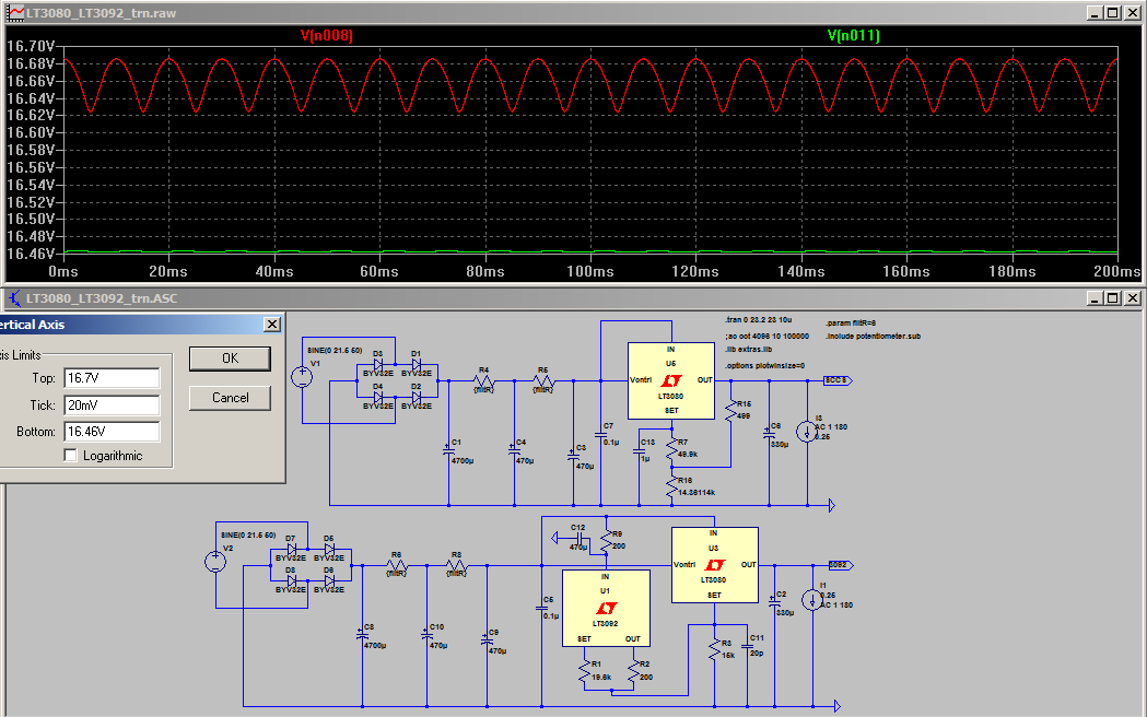
One interesting (at least I thought so) observation was how the size of the cap on the adj pin of the LT1086 changes the shape of the ripple on the output. See below for examples.
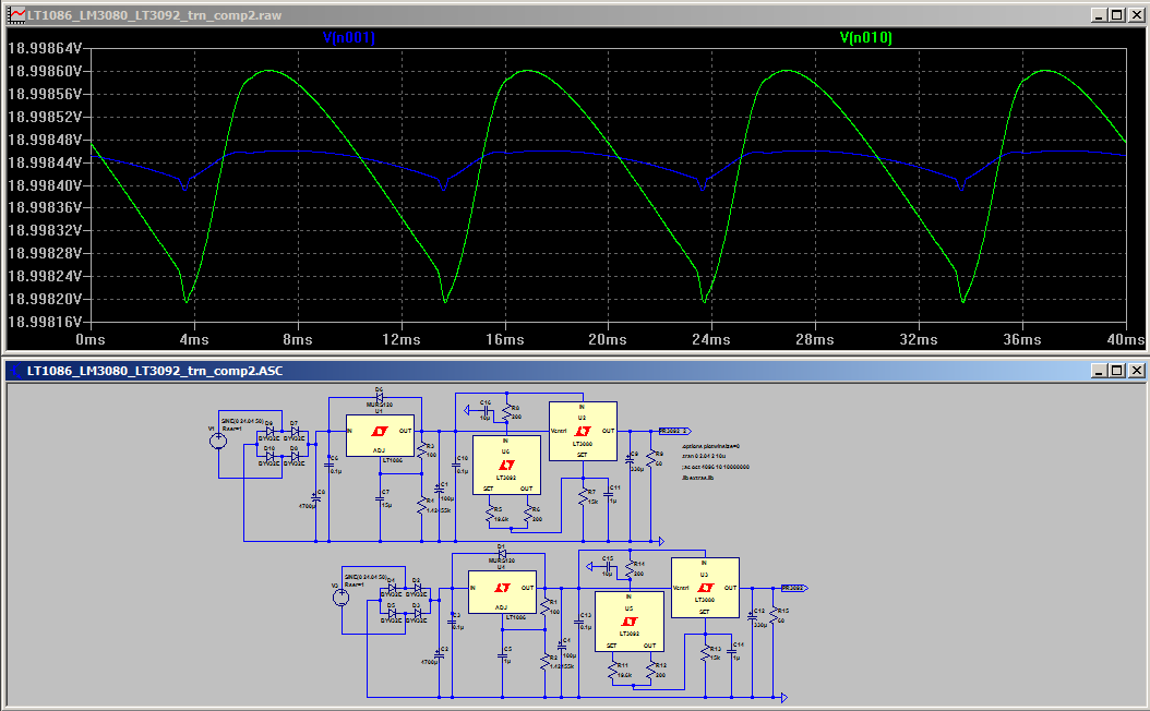
This one the green trace is with 1uF on the adj pin, and the blue trace is with 4.7uF.
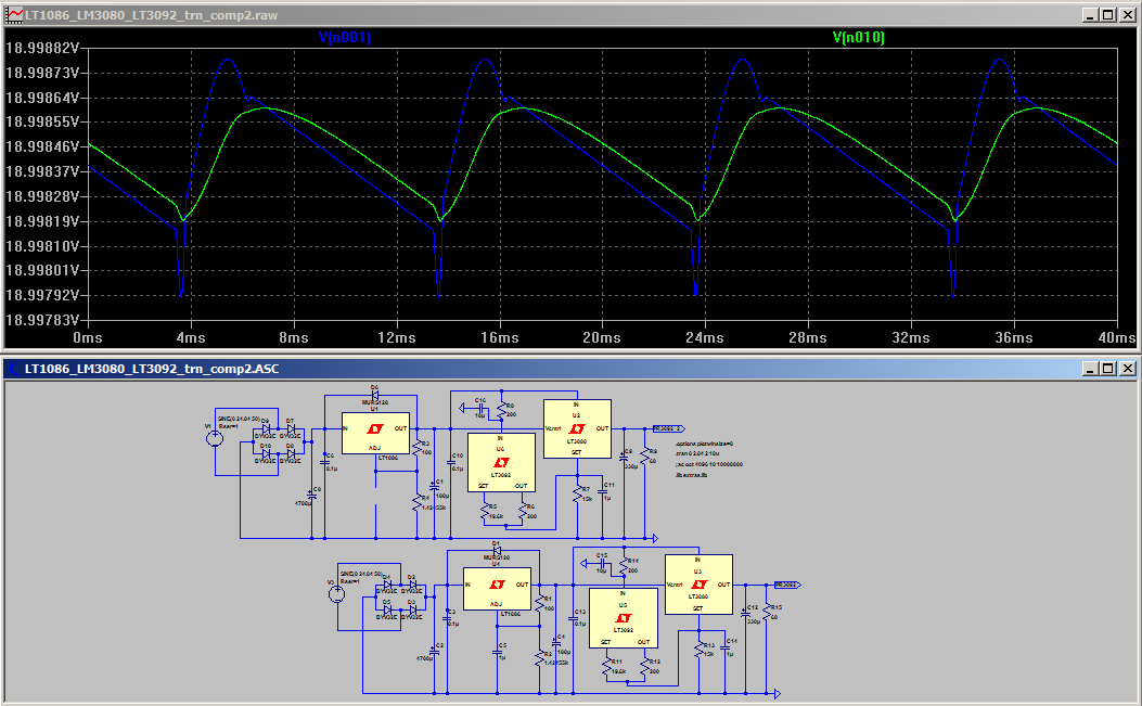
This one shows what happens when we take away the adj cap altogether (blue trace) green is again the 1uF adj cap.
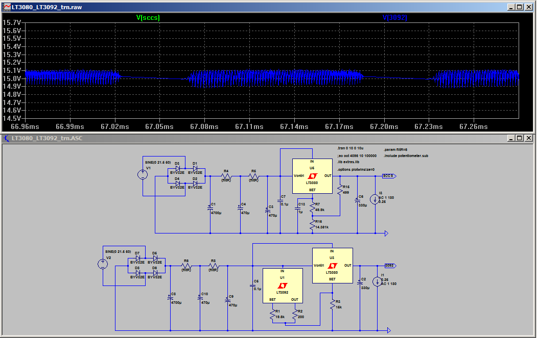
I decided to pair up the LT3092 version of the circuit with the pre-reg. This is where it shows its worth! It didn’t matter what I changed it just worked. No oscillations. So perhaps stability is its selling point. So much for the simpler circuit! :rolleys:
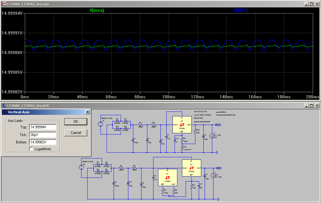
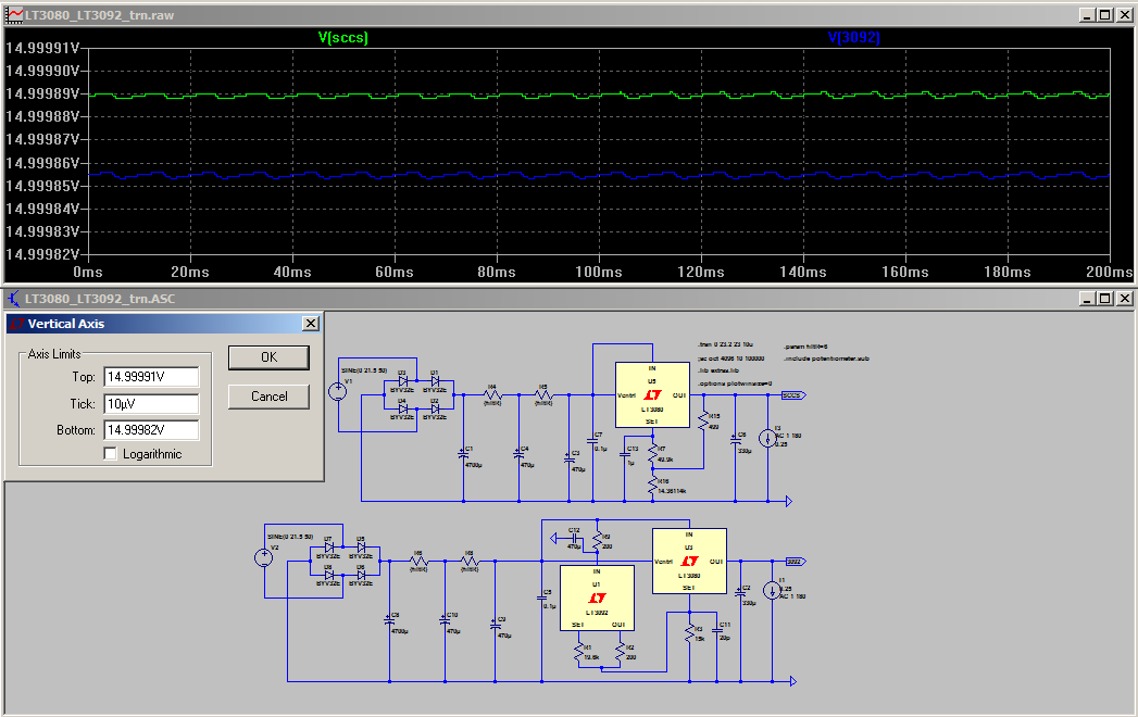
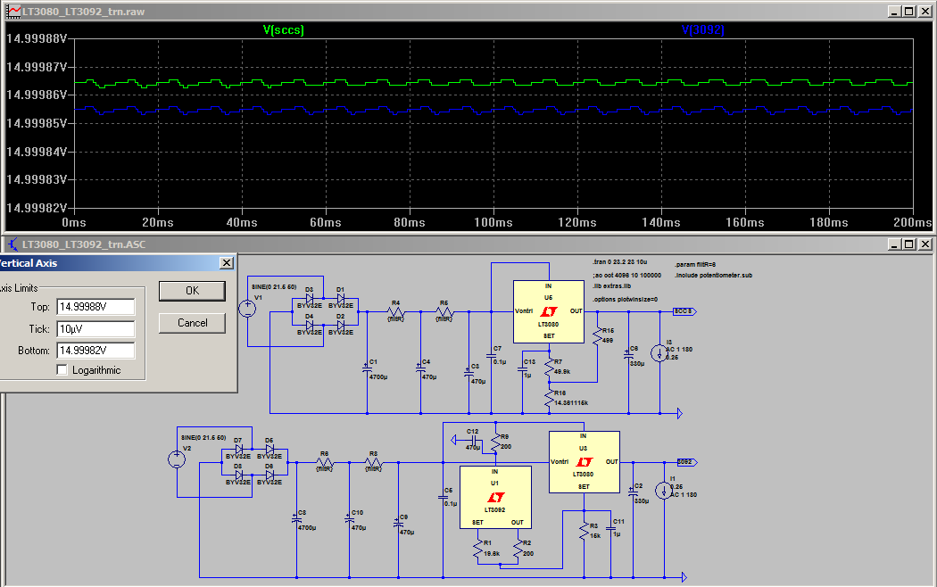
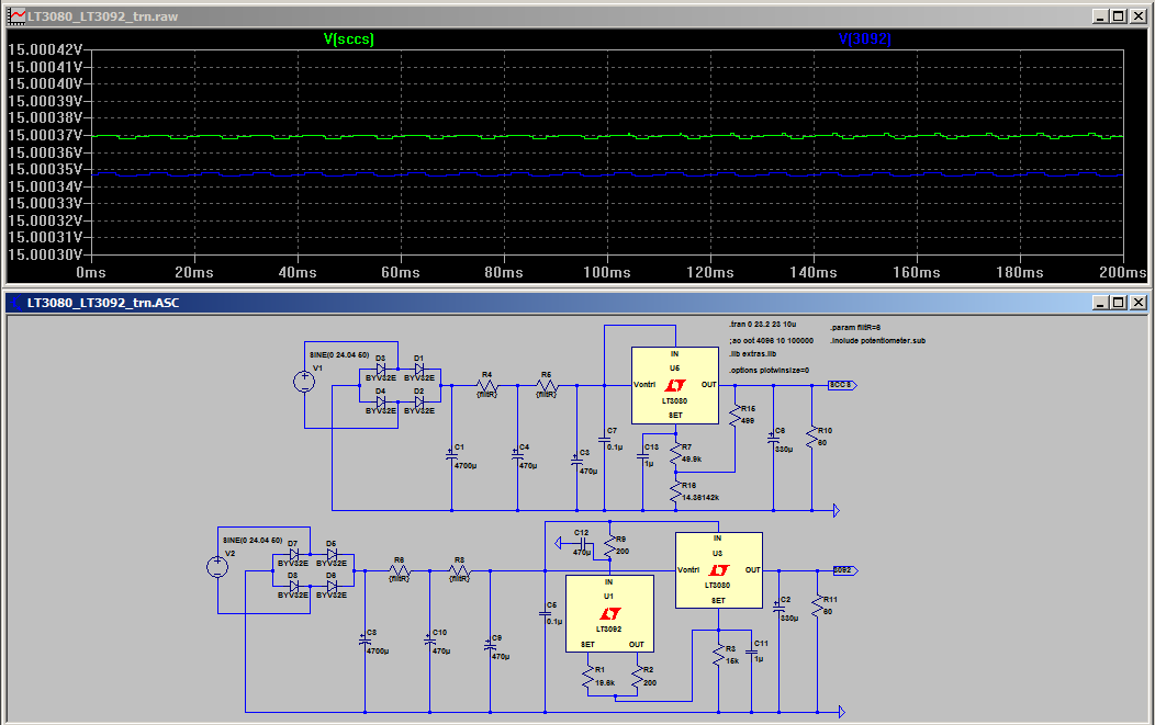
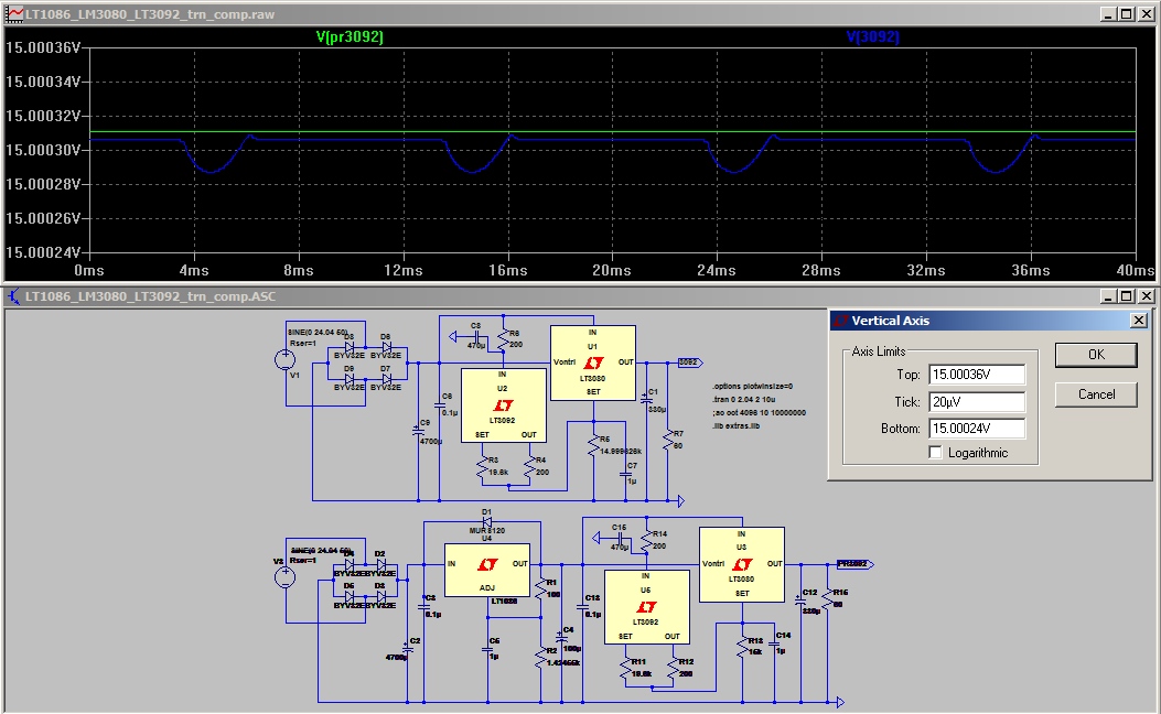
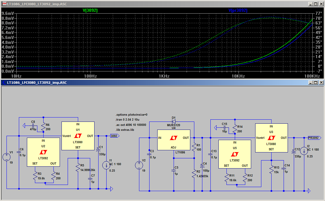
Below is a comparison of the LT3092 circuit and the LT3092 circuit with LT1086 pre-reg. It looks dramatic until you see that the tick size is 20uV. Since the schematic is a bit small I’ve included an enlarged version. Note that the 470uF cap on the feed to the LT3092 can be dropped dramatically in the pre-reg version.

For completeness an impedance plot is also shown below. Interestingly the one with the pre-reg seems to be a bit better over about 5Khz, though I’m uncertain why this would be.
So that is where I am at presently. I’m leaning towards using the LT1086 as the pre-reg (if I go with a pre-reg at all) simply because I don’t need to worry about the sensitivity of the LT3080’s set pin when using a single resistor. It doesn’t seem to make any difference with respect to the final performance, and it is cheaper, especially if I opt for the TI LM1086.
I’m in two minds about whether it is even necessary to worry about the pre-reg though. 20uV of ripple is really not very much at all. If you want perfect then (in sim land) the pre-reg delivers, but in the real world will it even matter (almost certainly not).
So I’m at a point where (so far) it seems that the variation with an LT3092 is winning out. I probably should do some sims with a square wave generator as the load and see what the transient response is like. I’ve done that (for real not sim) on my YARPS supply and it didn’t look very nice on the scope!
I think I have a 555 square wave generator spice circuit I put together somewhere. I’ll need to dig it up. This post has been way too long coming though so I will stop now and get this post posted
Around this point I started thinking I’m getting into overkill territory again and that the caps and resistors I was using for getting the ripple down pre reg, were probably more expensive than putting in a second reg for pre-filtering. I initially put in a LT1086 with just a 4700uF cap before it and that reduced the ripple enough to get no detectable ripple on the output (at the current I was driving).
At this stage I hadn’t re-visited the passive CCS, it now looked like an option again
I decided to give it a try as it seemed like I would now be able to do it without any problems with excessive ripple on the output (I hadn’t tried the 1uF cap on the set pin at that stage). The first attempt at using the simple ccs circuit with an LT1086 pre-reg oscillated! I’d copied the jbau implementation of the lt3086 which had 330uF on the adj pin.
Reducing the adj cap to 10uF solved the issue (or so I thought*).
I then thought, the single resistor LT3080 is also a candidate for a pre-reg. In the sims I did it really didn’t make any difference which of these two options I chose. The LT3080 as a pre-reg is slightly simpler due to the single set resistor (which in the case of a pre-reg will not really need adjustment, but it will still need careful layout to deal with the potential noise pick up on the set pin with the 10uA current.
*When I started to do the sims for this part of the write up I discovered that the combination of the LT1086 pre-reg and the simple CCS version of the LT3080 circuit was quite fussy! It oscillated in many configurations! The presence of a 0.1uF cap before the LT3080 might cause it to oscillate. It might oscillate with a 1uF cap on the set pin and a certain sized cap on the adj pin of the LT1086, change the size of the cap on the ajd pin and it may be the other way around. It oscillates if you drop the size of the post rectifier bridge cap below about 1500uF (this may be related to the size of ripple on the output of the LT3086). I decied that this variability is probably not very desirable.
The magnitude of the oscillation is not great, but it is there and I don’t like it, so I’m thinking that this is not a viable option. Perhaps in a real world situation rather than a sim it won’t happen… but my experience has been that it is more likely that you won’t get an oscillation in a sim that you DO get in the real world, so if the sim says it will oscillate, then it probably will!
One interesting (at least I thought so) observation was how the size of the cap on the adj pin of the LT1086 changes the shape of the ripple on the output. See below for examples.
This one the green trace is with 1uF on the adj pin, and the blue trace is with 4.7uF.
This one shows what happens when we take away the adj cap altogether (blue trace) green is again the 1uF adj cap.
I decided to pair up the LT3092 version of the circuit with the pre-reg. This is where it shows its worth! It didn’t matter what I changed it just worked. No oscillations. So perhaps stability is its selling point. So much for the simpler circuit! :rolleys:
Below is a comparison of the LT3092 circuit and the LT3092 circuit with LT1086 pre-reg. It looks dramatic until you see that the tick size is 20uV. Since the schematic is a bit small I’ve included an enlarged version. Note that the 470uF cap on the feed to the LT3092 can be dropped dramatically in the pre-reg version.
For completeness an impedance plot is also shown below. Interestingly the one with the pre-reg seems to be a bit better over about 5Khz, though I’m uncertain why this would be.
So that is where I am at presently. I’m leaning towards using the LT1086 as the pre-reg (if I go with a pre-reg at all) simply because I don’t need to worry about the sensitivity of the LT3080’s set pin when using a single resistor. It doesn’t seem to make any difference with respect to the final performance, and it is cheaper, especially if I opt for the TI LM1086.
I’m in two minds about whether it is even necessary to worry about the pre-reg though. 20uV of ripple is really not very much at all. If you want perfect then (in sim land) the pre-reg delivers, but in the real world will it even matter (almost certainly not).
So I’m at a point where (so far) it seems that the variation with an LT3092 is winning out. I probably should do some sims with a square wave generator as the load and see what the transient response is like. I’ve done that (for real not sim) on my YARPS supply and it didn’t look very nice on the scope!
I think I have a 555 square wave generator spice circuit I put together somewhere. I’ll need to dig it up. This post has been way too long coming though so I will stop now and get this post posted
Attachments
Last edited:
Given the comments on noise earlier in the thread you might find this article on making the output of noisy regulators quiet of interest..
Finesse Voltage Regulator Noise! |
Following with interest. I use LT108x series mostly for filament regulators, and used positive regulators for both + / - outputs mostly to reduce parts inventory and the need for different regulator boards. Works absolutely fine as you would expect.
Finesse Voltage Regulator Noise! |
Following with interest. I use LT108x series mostly for filament regulators, and used positive regulators for both + / - outputs mostly to reduce parts inventory and the need for different regulator boards. Works absolutely fine as you would expect.
Looks like the LT3092 is only available in SM packages. So what else is new, right??
Perhaps the SOT-223 version can be soldered without the aid of a "microscope".
Looking forward to see if the '3092 is what's needed to get the '3080's lackluster performance up to par.
I received 2 samples of the '3080 from Linear last week. Hope I can use them with help of Tony's research and simulations.
Thanks Tony!
Very interesting thanks Kevin!
I ended up having to do some house work yesterday so no progress on the next installment but maybe tonight
I thought i checked that the 3092 was available in to-220 but apparently not. I chose it mainly out of laziness as LTspice already had one in its library
On the lackluster performance, I'm not seeing it, but perhaps I need a better way of testing the output impedance. I will need to dig a bit deeper on that one.
Tony.
Hope you aren't too disappointed with part three ammel
Not at all. Looking good!
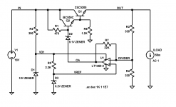
Here's a different way to get flat, frequency-independent output impedance magnitude and phase: build a voltage regulator out of discrete components plus an opamp, and then carefully tailor the frequency response so it's flat, Flat, FLAT!
There are perhaps three things to notice here:
1. The output impedance's magnitude is flat to 1 MHz, and the output impedance's phase is flat to 100 kHz
2. There are no conjugate matching networks. No inductors, no output capacitors, no infringements of J.Bau's patent
3. Slightly unusual opamp feedback loop. Think: Thevenin equivalent ckt
_
Attachments
Nice! I assume a variation of the super-reg.
I was looking to do something simple, but as you can probably see from the way this thread is trending, it has been getting more complicated though I've still to do part four. I'll never get something as good as a discrete regulator using pre packaged regs, but I like experimenting, and this is a level that I'm able to do so
No risk of infringing jbau's patent. At most I'd look at adding a very small series resistance on the output circa 3m ohm. But since I'm still a bit doubtful about the simulated results (ie around 0.6m ohm output impedance when others have said they measured 10 mohm and 60m ohm, it may be ******* in the wind....
Tony.
I was looking to do something simple, but as you can probably see from the way this thread is trending, it has been getting more complicated
though I've still to do part four. I'll never get something as good as a discrete regulator using pre packaged regs, but I like experimenting, and this is a level that I'm able to do so No risk of infringing jbau's patent. At most I'd look at adding a very small series resistance on the output circa 3m ohm. But since I'm still a bit doubtful about the simulated results (ie around 0.6m ohm output impedance when others have said they measured 10 mohm and 60m ohm, it may be ******* in the wind....
Tony.
Nah, post #10 is more along the lines of a dumbed down Sulzer regulator since the opamp is powered from the input rather than from the output. Unlike Sulzer (and unlike Jung's super-regulator), the VREF is also powered from the input rather than from the output.
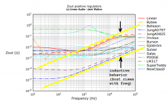
The "trick" here is to actually do something about the opamp's single pole rolloff. Normally the opamp gain falls with frequency, so the voltage regulator's output impedance (proportional to 1/gain) rises with frequency, and the whole circuit acts like an inductor as jbau measured. You can see this same effect in the plots of impedance vs frequency that Jack Walton measured & published in Linear Audio magazine, copied below.
_
Attachments
Ok I expect that the ripple rejection won't be as good then? Perhaps requiring a pre-reg.. You have given me yet another distraction for playing with once I finish with the LM3080 stuff!
Kevin: certainly the case for me!! I suspect that Jack and Tom though are a little better equipped than the typical diy'er though. Unfortuantely Jacks images are no longer available so I can't see if they correlate to what I am seeing (but two orders of magnitude higher)...
Tony.
Kevin: certainly the case for me!! I suspect that Jack and Tom though are a little better equipped than the typical diy'er though.
Unfortuantely Jacks images are no longer available so I can't see if they correlate to what I am seeing (but two orders of magnitude higher)... Tony.
Last edited:
> I decided I needed a regulated power supply for my new concept for an active crossover.
Why? Most any op-amp, or good discrete amp, is not too fussy about exact supply voltage, and will be fine with the ripple off a simple C-R-C filter.
Define (to yourself) "Why?" you need something more.
And "What?" parameters matter. Exact 15.000V regulation? -123dB ripple rejection? Rails solid as frequency goes toward radio waves?
Most of the 49 cent regulators will give a voltage +/-5% of nominal and +/-2% of their initial value over wide swings of input voltage and temperature, and any reasonable load current.
Most of these can also reduce any reasonable raw ripple to plenty-good for any sophisticated amplifier, though maybe not for very simple (1 transistor) gain stages.
Note that nearly all the music you listen to was produced on gear powered by fairly basic regulators, with maybe 10r and 100uFd+0.1uFd on each card to control supersonic rail impedance and sneakage. And ran through a lot more such stages than your crossover has.
I see you plotting Z vs Freq. Does this matter? Maybe some. (Sometimes a lot.) But look at your regulator. Any regulator is an error amplifier and a pass device. Simple/cheap amps and passers can do very well DC-100Hz-1KHz. Unless the designer is obsessing about >1MHz, you can just assume lower performance above 1KHz. (This does not mean "worse ripple rejection" unless your raw DC is astonishingly nasty.) Oxen don't dance. Commodity regulators are built with Silicon "oxen", pull the load, but are not MHz nimble.
Everybody from Jung to Johnson has worked on combining fast amplifiers with fast power devices, to extend low-Z performance past 1MHz. Same as is done in audio amplifiers for extended response and speed. Faster power devices are possible, but not in commodity regulators because nobody (except audiophiles) expects the regulator to be "perfect to infinity", designers generally treat the >1MHz problems locally in the powered circuit.
> look at ripple rejection. ...the ticks are 30uV
So 5 microVolt rms ripple. Your crossover amps may have near 1uV hiss. At crossover level, studio ambient and mike hiss will be in the dozens-uV range. If your crossover amps have any PSRR at all, wall-juice ripple is the least of your corruptions. (I would not fret a milli-Volt of ripple on about any chip amp or non-crude discrete amp.)
I understand the joy of poking SPICE. I have some lost weeks and many Megs of files from fighting mind-puzzles to prove/disprove a point. But if your goal is to listen to music, don't get lost inside the SPICE. Show it may work without gross problem, then build it and listen to it. Ripple-buzz is obvious but more often poor layout than bad filtering. MHz squirreliness may be harder to identify, so you never omit local bypassing with RF-happy caps.
Hi PRR, I tend to obsess about things that don't matter, this blog post from 2009 should give an idea http://www.diyaudio.com/forums/blogs/wintermute/119-problem-wanting-get-best-performance.html
I'm a little surprised by the comment that a simple CRC should suffice, considering the amount of trouble people seem to go to creating regulated supplies for audio (many of whom are actually pretty accomplished engineers).
I actually fall into the category where I suspect that I wouldn't actually be able to hear a difference, but since some people say they can, I might as well address things that just maybe might actually make a difference.
The thing I latched onto originally was supply rail symmetry (something I haven't addressed as yet in this thread) and the thing that started my on this thread, flat impedance and phase throughout the audio band. I figure they are things that may not make any difference in reality, but it certainly can't hurt if done properly (ie not at the expense of something else).
I did do exactly what you suggest with the YARPS power supply (and this time around I have been much less obsessed (if you can believe it). I simmed it to make sure it was likely to work. I breadboarded it and verified it did in fact work, then I built it on verro board, and it has been in use for some years. I'm hoping that this iteration is a bit faster than the first one (which was a big leap for me from building kits that someone else had designed).
In the end, yeah I could just use a CRC though with 250mA current draw the ripple is still pretty big even with 4700 3r3 1000 3r3 1000 and I might be fine, or I could just buy the super reg boards, from the diyaudio store and be happy with that. However, going down this path I'm actually learning something (whether or not is important is another matter) but it gets the grey cells working..... It's nice to actually design something (even if it is pretty much just from the datasheet) build it, test it, and use it. That's primarily what this thread is about my own journey, and perhaps that might just inspire someone else to try something that they might otherwise not have.
Tony.
http://www.diyaudio.com/forums/blogs/wintermute/119-problem-wanting-get-best-performance.html I'm a little surprised by the comment that a simple CRC should suffice, considering the amount of trouble people seem to go to creating regulated supplies for audio (many of whom are actually pretty accomplished engineers).
I actually fall into the category where I suspect that I wouldn't actually be able to hear a difference, but since some people say they can, I might as well address things that just maybe might actually make a difference.
The thing I latched onto originally was supply rail symmetry (something I haven't addressed as yet in this thread) and the thing that started my on this thread, flat impedance and phase throughout the audio band. I figure they are things that may not make any difference in reality, but it certainly can't hurt if done properly (ie not at the expense of something else).
I did do exactly what you suggest with the YARPS power supply (and this time around I have been much less obsessed (if you can believe it). I simmed it to make sure it was likely to work. I breadboarded it and verified it did in fact work, then I built it on verro board, and it has been in use for some years. I'm hoping that this iteration is a bit faster than the first one (which was a big leap for me from building kits that someone else had designed).
In the end, yeah I could just use a CRC though with 250mA current draw the ripple is still pretty big even with 4700 3r3 1000 3r3 1000 and I might be fine, or I could just buy the super reg boards, from the diyaudio store and be happy with that. However, going down this path I'm actually learning something (whether or not is important is another matter) but it gets the grey cells working..... It's nice to actually design something (even if it is pretty much just from the datasheet) build it, test it, and use it. That's primarily what this thread is about
my own journey, and perhaps that might just inspire someone else to try something that they might otherwise not have. Tony.
Actually post #10 contains a pre-regulator and a pre-pre-regulator.
(R2-D1) knocks big chunks off the ripple waveform and gives the opamp a relatively clean supply; its enormous PSRR then goes to work, rejecting what little ripple it sees.
The second stage (R5-D3) further attenuates ripple so that VREF is clean and pure. Those paranoid about noise can replace D3 with the low noise LM329 IC, and then post filter VREF with one or two stages of RC lowpass. The opamp's input bias current is low so you can use hefty resistors here as long as you don't mind sloooooow rampup at power-on. This is one place where I might use a 3-terminal feedthrough capacitor link for maximum attenuation.
As long as VREF is clean and as long as the opamp's (supply ripple X PSRR) is teeny tiny, NFB will do its job and prevent the output from rippling. If you're still nervous, plop down an LM2940 ultra low dropout adjustable regulator, upstream of post #10. Get another 75 dB of ripple attenuation @ 120 Hz, at the very low cost of four new parts and one extra volt of headroom. Short circuit protection too.
Of course ripple attenuation on VREF improves by a factor of 10X to 100X if you replace R2 and R5 by JFET+trimmer current sources. Or if you hate JFETs, BJT+2diodes+2resistors current sources. It's a simple voltage divider: (Ripple out) = (Ripple in) * (Zbot / (Zbot + Ztop)) and using a current source means Ztop=Infinity. Thus (Ripple out) = Zero.
Last edited:
The opamp and its negative feedback network work very, very hard to ensure that its two input terminals are the same voltage.
Thus V(DIVIDER) = V(VREF)
Since V(DIVIDER) is the output of a voltage divider made of R3 and R4, we have
V(DIVIDER) = (R4 / (R3 + R4)) * VOUT
Zener diode D3 sets V(VREF) = 6.2V.
Substituting these expressions into the equation "V(DIVIDER) = V(VREF)"
VOUT * (R4 / (R3 + R4)) = 6.2V
and finally
VOUT = 6.2V * (R3 + R4) / R4
- Status
- This old topic is closed. If you want to reopen this topic, contact a moderator using the "Report Post" button.
- Home
- Amplifiers
- Power Supplies
- From LM317 to LT3080 an LTSpice Journey