I am making a PSU that is going to leave 490v.and its working except that I dont know how many ohms the trafo should be at right now it is at 35,633ohm.
But I think I get more accurate result if I set it to 1 ohm...
I would be glad to know wich is right before I order a custom made toroid.

If I calculate 379v X 1.41 =I get 534v witch don make sence..
To get the most accurate result set the transformer resistance to what the transformer resistance will be. This is secondary resistance plus transformed primary resistance. I think PSUD2 will do the calculation for you if you input the two DC resistances.
What is it that doesn't make sense to you?
What is it that doesn't make sense to you?
1 Ohm suggests a 1,000VA transformer. Since you only have a 50 Watt load, a 1,000VA lump is a lot to pay for, ship, and lift.
Transformers I have used and abused say that you are probably facing 20 to 30 Ohms transformer resistance. 1 Ohm is awful optimistic and you will be disappointed by reality.
IF you know rated V and I and Regulation, PSUD has that calculator hidden under a small arrow on the transformer dialog box. If you do not know the rated reg, for a PT this general size I would pencil 12%.
Ryssen. Add in a delay before it calculates results.
that way you see what is happening during the operational state.
Have a look at the ripple current in the first capacitor.
Now swap the capacitor values and look again at the ripple current.
You need to specify capacitors that can handle that ripple current in the longer term. It is this that heats up the capacitor and brings on a shortened lifetime.
A small bank of much smaller capacitors may be a cheaper way to obtain adequate ripple capacity in that first C.
4off 100uF @ 630Vdc might be a lot cheaper than 470uF 630Vdc and buy you additional ripple capacity.
Did you mean to type 47mF into PSUD2?
that means 47milli-Farad = 47000 micro-Farad.
Last edited:
You mean that what I calculate is voltage without a load?If I calculate 379v X 1.41 =I get 534v witch don make sence..
PSUD 2 Caculated the resistance to 35,9 ohm.
Yes I saw that error with the mF and uF ,will try to simulate again.
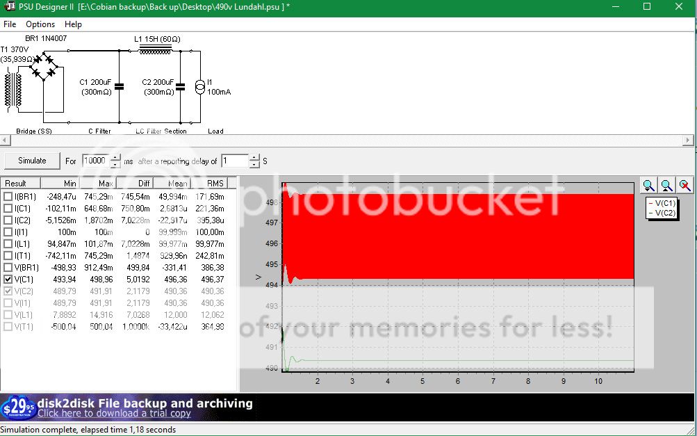
There's still a lot of ripple from the start up.
increase your delay to 3s.
Reduce the input cap to 100uF and keep C2 at 200uF
Then compare to using 200 for C1 and 200 for C2 and finally 200 for C1 and 100 for C2
You can then assess the value you get in mains ripple per uF of smoothing.
Look at Ic1. That's your long term ripple and your ripple capacity must comfortably exceed that.
Can the current to the load increase?
What effect does that have on ripple currents and output voltage?
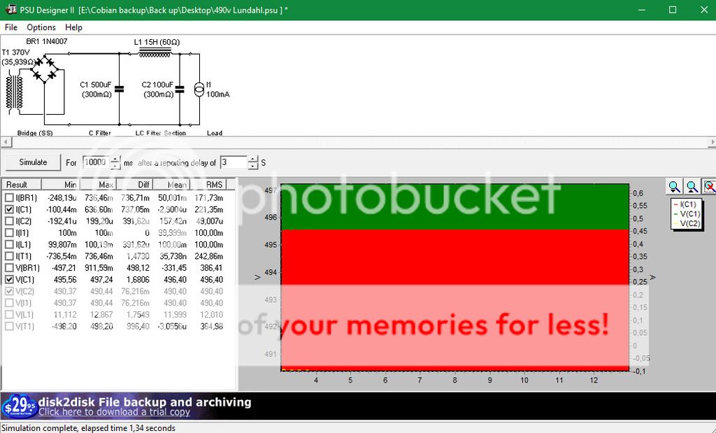
I lowered the cap at output to 100uF and with 200uF at C1 the green area is at 50% of the area.
Now I´m using 500uF and the gren area is less I even tried 1000uF and it got better.but that is starting to get expensive for uF..
")
Is it okay to load more and more at C1?
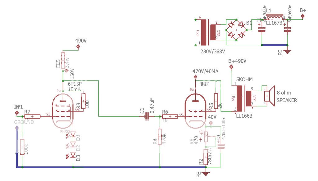
The load is a tube SE (Class A) amp thats 6P15P drivertube at 10mA/channel and 807 40mA/channel.
I increased the output to 130mA and the voltage went down 7 volts and the ripple went up a bit.(This was with 500uF C1)
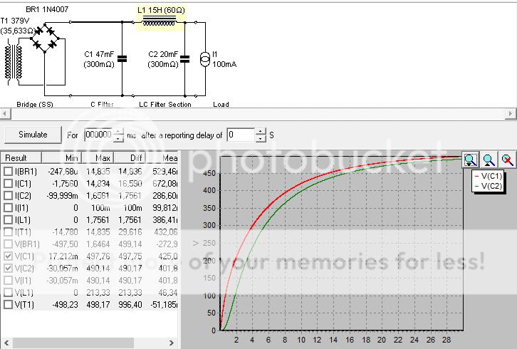
Change "For 10000ms" to 100ms
you can zoom in on the plots, or click on the scales and manually change to the scales you want to see. eg Voltage from 495 to 496
That way you get to see the shape of the sawtooth waveform at Vc1 and Vc2.
A spiky shape tells you there is a lot of high frequency content. A rounded shape tells you there is less HF.
Look at the ripple voltage on Vc1
The diff is stated in the table as 1,6806, that is Vripple = 1.68Vpp, whereas Vc2 Vripple = 0.078Vpp, i.e the LC has reduced ripple by >26dB
What does your amplifier need?
That's what PRR is asking you to consider.
The amplifier is separated from C1 by the impedance of L1 (or the resistor if used).
The amplifier mainly draws it's operating current from the LAST capacitor in the PSU. This needs to be as big as the amplifier DESIGNER tells the Builder to use.
Look at Ic1 = 0.636A
You need at least this ripple current capability for the bank of capacitors forming C.
If your output changes from 100mA, then ripple current will change.
Last edited:
I used a single 250uF cap to feed a stereo EL34 PP - current consumption around 100mA/channel. PP will partly cancel hum, but why do you need such low ripple? Be aware that once you get beyond a certain point the ripple is set by your grounding details and circuit loop size, not the cap values.Ryssen said:I lowered the cap at output to 100uF and with 200uF at C1 the green area is at 50% of the area.
Now I´m using 500uF and the gren area is less I even tried 1000uF and it got better.but that is starting to get expensive for uF..
Is it okay to load more and more at C1?
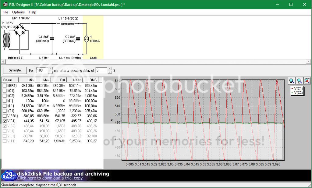
This is with 8+8uF,one thing I had to do was to raise the trafo sec voltage with 18volts to get 490v at C2.And then the voltage at C2 is 541 v ,wich accoring to PSU Designer will raise to 545v unloaded.
Does the red spikes mean I should add more uF to C1 then?
It is a self made schema for the amp,(I can upload it)
The red trace is the typical sawtooth waveform one gets from a PSU.
You can read theVripple from the plot or from DIFF of Vc1
The green trace is the waveform after the second filter. Note this is very rounded showing that the LC filter has removed most of the HF harmonics leaving substantially the 100Hz of the rectified mains.
Again you can read the DIFF value for Vc2.
Will the amplifier work with 8uF for C2? What is specified in the design?
Last edited:
How do I tell that?Will the amplifier work with 8uF for C2? What is specified in the design?
Obs I changed the caps to 8uf in the schema..I former used 47uF in the schema.
You have 1.65V pk-pk ripple with two 8uF caps. This is roughly 600mV rms. If not attenuated this will give you approximately -54dB hum. You will probably want a bit less than this, but it shows that 8uF caps do not give a totally ridiculous result. 32+32uF would be about 24dB better i.e. -78dB hum.
Your amplifier may have some, or a lot of, PSRR (Power Supply Rejection Ratio).
If wired correctly you may get similar or less hum than what is on the supply rail.
That is what the circuit Designer DESIGNS for and makes adjustments till he hits his performance targets.
You can test using a high hum PSU and find what PSRR you get, then decide how much lower hum to need to hit your target. But you have to wire it up correctly BEFORE you start this analysis.
As I didn't make that point it is perhaps unsurprising that you didn't get it. You need to decide what level of hum you need - but it is probably not as low as you might imagine. Always bear in mind that in electronics, as in all engineering, concentrating on one thing means compromising on something else - either because physics causes this, or because your attention has been diverted away.Ryssen said:And now to the point that I don´t get..Is there no point in getting lower hum than -78db then?
A common newbie mistake is to believe that the PSU has to have virtually no ripple at all so huge caps are used. This might be OK if PSU ripple was the only source of hum in an audio setup and large capacitors were guaranteed to reduce ripple with no adverse effects, but that is not the case.
- Status
- This old topic is closed. If you want to reopen this topic, contact a moderator using the "Report Post" button.
- Home
- Amplifiers
- Power Supplies
- PSUD2 Gurus, I need help...