> check with the scope
Who is paying for this thing? The 'scope? Or your EARS?
A fancy 'scope can be dialed down and down until it WILL find hum, even if it would never be heard on a speaker.
____________
SE triode has poor PSRR, and I would expect it to want more filtering than say a two-6V6 into an open-back (bassless) guitar cabinet.
8uFd is very old-school. 40uFd was a mainstay of the 1960s. SE triode may need 40u-10H-40u.
If you do have a 'scope, and any decent amp and speaker, mix (two resistors) line source and finger-buzz into the amp. Adjust buzz level until it is not audible. Read 'scope. That's *your* buzz tolerance (very roughly).
Last edited:
Ok,the speakers at my workbecnh is about 91db sensitivity,and the mid speakers (where i plan on using the SE amp) is 100db so they "maybe" need some extra uF.
Thank you all I´ll keep this things in mind when I build,and afterwards to....")
Hello Ake, I've been using PSUD extensively, and it is a very helpful tool indeed. Use it mainly to build supplies for SE use, with sensitive speakers.
Here's my suggestions:
With the 96-100dB sensitivity range you'll need about 2mV or less hum for a quiet supply.
With a single pi filter supply it is impossible to get a dead quiet SE supply. You can get it reasonably quiet. Concrete example: 230uF-4H-230uF results in hum audible from 1ft of the driver. However, big C1 (over 40uF) means big current draw at turn on and big beating on the power transformer (plus, no tube rectification, sand only). PSUD indicates for C1 20uF is the best compromise. It will give you a good voltage regulation, about 95% of the highest achievable voltage and easy on the transformer. Even on PP gear such as Quicksilvers with high C1 (300uF!), adding an additional 20uF-33R filter stage in front (so the 300uF C1 becomes the C2) makes for a nice improvement in dynamics and much more relaxed sound. Keep the last C (that feeds your output stage) around 300uF - that seems to be the optimal capacitance for best dynamics and reserves. Yes, a 8uF-8H-8uF-8H-8uF is a very nice recipe for a SET supply - will give superb midrange but dynamics will be very limited. And 8uF-8H-8uF will need lots of feedback to keep it quiet. Slap in 100uF instead of the last two 8uF and you'll have the impression that the power of the amp went up by a factor or two.
I like to make my supplies DEAD quiet. You can do that with two pi filter sections, choke each (CLCLC). An excellent recipee is 40uF-4H-80uF-4H-80uF. (PSUD gave microvolt and picoamp level of hum for that supply.) I have that in my SE Darling amp, and it's so quiet that when we hooked it up to a Lowther horn (100+dB) we did not hear any hum at all, even with ear pressed to the whizzer cone. We thought the amp is not on... were troubleshooting it for a good while, until someone had to idea to hit play on the CD and music came pouring out.
In short, you could think that dead quiet supply is overkill, since when you cannot hear hum at 1.1ft, at your listening position it certainly will not be a bother. However, there is still a difference. While you cannot identify it as hum, your brain still picks it up as subliminal stress. With a dead quiet supply the music is more relaxed, natural and more low level detail.
When we model we always model for static, zero signal mode. However, when load increases ripple increases drastically and modulates the music, creeping up into the audible range.
Is it of any use of using a CLCRC filter?
Hello Ake,
Yes, there is a good use. When you do not have enough space for a choke, it is a good solution to take care of residual hum. It will Decrease the ripple quite a bit, and if you keep R small (100R or less) then it will not affect regulation much.
When you have very high inductance choke, it can create a huge turn-on overvoltage (600V for a 500V supply) - always run a PSUD simulation if that is the case with the supply you want to build, and rate the caps accordingly. Following the CLC with an additional RC will cut that high spike significantly down, greatly extending cap and tube life.
Unfortunately C1 is making the biggest impact on filtering but we have to keep it down. A good rule to follow when building a power supply is to keep C1 smallest, and progressively increase C size, having the last C as the biggest. Otherwise you will get motorboating - the big cap sucking charge back from the downstream smaller cap, creating instability.
That is not what causes motorboating. Motorboating is caused by the supply having significant impedance at a frequency where the amplifier still has some forward gain. However, your prescription of having a large cap at the end is sound - this will reduce supply impedance at low frequencies.janos said:Otherwise you will get motorboating - the big cap sucking charge back from the downstream smaller cap, creating instability.
Thank you for that. I have not seen it put like that before.Motorboating is caused by the supply having significant impedance at a frequency where the amplifier still has some forward gain.
Hi Ketje,
1uF is way too low, the program cannot make any sense of it. You have to make these caps 25uF-200uF to get anything useful out of it in your current schematic.
Also, for 11V, these values are way too low. Try 10.000uF for the voltage doublers, and 10.000uF for the first filter cap.
Use 100uF range for high B+ voltage (hundreds of V), and 10.000uF range for low voltages.
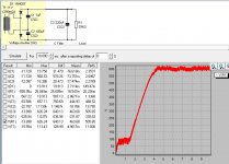
The simulation the way you did tells you how the supply turns on, but has no information on the ripple. Insert a time delay of 30S to see what your ripple looks like, and how quiet it is.
Good luck;
Janos
1uF is way too low, the program cannot make any sense of it. You have to make these caps 25uF-200uF to get anything useful out of it in your current schematic.
Also, for 11V, these values are way too low. Try 10.000uF for the voltage doublers, and 10.000uF for the first filter cap.
Use 100uF range for high B+ voltage (hundreds of V), and 10.000uF range for low voltages.
The simulation the way you did tells you how the supply turns on, but has no information on the ripple. Insert a time delay of 30S to see what your ripple looks like, and how quiet it is.
Good luck;
Janos
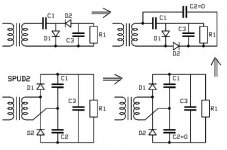
What i tryed to do was simulating a voltage doubler for making a negative bias voltage from heater windings.One with one side of the transformer is grounded.
If you set C1 or C2 to zero the circuit is in principle the same.The program refuse values smaller then 1nF, but with the other large enough it could work.But there comes a message about some timestep error ? And with accepted values i get rediculous results.
Mona
If you set C1 or C2 to zero the circuit is in principle the same.The program refuse values smaller then 1nF, but with the other large enough it could work.But there comes a message about some timestep error ? And with accepted values i get rediculous results.
Mona
Attachments
Last edited:
PSUD2 is too simplistic for your need - as it only has the most basic rectification topologies. I'm not sure if PSUD3 is targeting that rectifier circuit - check the upgrade thread perhaps.
Using part values that are not typical within PSUD2 can cause computing step issues, and throw up warning messages. If you want to keep trying to play - then suggest start with typical part values and then reduce those values and observe waveform changes for 'quirky' or noisy waveform responses to know that you have pushed the program to its limits.
LTspice would do what you want.
> 1uF is way too low
That is marginally acceptable considering the high 25K load. We expect like 30V, so ~~1mA load, 1uFd per mA, is 1uFd.
I think PSUD goes off in the weeds because the Doubler "should" have same-value caps at C1 and C2. That's not essential, no. But PSUD takes some liberty with its approximations, and this wild asymmetry has it buffaloed.
Compare attachments, 1uFd+100uFd (your case) and 100uFd+100uFd ("more sensible"). With equal-size C1 C2, PSUD gives a very likely answer.
For further fun (not shown), I deleted C3 (it is redundant with a proper set at C1 C2) and tried C1=C2=10uFd in respect of the 25K load. I get 29V with 1.6V ripple, a bit more buzz than I usually want but fine for many side-jobs or as food for further filtering.
> one side of the transformer is grounded.
Ah. PSUD doesn't do that. Nobody does everything.
> C2 to zero the circuit is in principle the same
I don't see that? You can't set one side of transformer +and+ one side of load common in PSUD? ... ... ah, making one of C1 C2 "infinite" it "should" be equivalent to common in-out. However when I try C2=1F, I get impossible variation of cap voltage, and different result with C1=1F (should be the same). PSUD is taking some simplifying assumptions and we have violated them.
And being a pre-SPICE boy, I say you can twist-up diodes and caps and get the Real World result faster than you can wrestle a computer. At 11VAC it isn't even a safety issue, nor does 25K@28V need hefty parts.
Attachments
This applies to all simulation or modelling.
You need to understand the physics to allow you to formulate the correct question. And then know enough to recognise whether the answer/prediction is giving a sensible number for the question asked.
Newbies are onto a loser trying to understand a piece of software written by someone else. Unless a full explanation of what is being done inside the string of equations and assumptions is given. That is unreasonable. The best we can hope for is a set of user instructions where the user has sufficient knowledge.
When people test software they usually test it with likely inputs (which should give a sensible result) and out of range inputs (which should be rejected). It is harder to test for all possible unlikely inputs, such as a voltage doubler with unequal capacitors. Duncan is aware that PSUD2 sometimes has convergence problems, but this generally only happens with unlikely inputs.
It may not be too late to get him to look at this particular issue, so post in the appropriate thread.
It may not be too late to get him to look at this particular issue, so post in the appropriate thread.
- Status
- This old topic is closed. If you want to reopen this topic, contact a moderator using the "Report Post" button.
- Home
- Amplifiers
- Power Supplies
- PSUD2 Gurus, I need help...