This question is in regards to a power supply I'm trying to design. The internet is chock full of zero-crossing detectors, but I can't seem to find one that will only detect as the cycle transitions from negative to positive. Is this really as difficult as I'm finding?
This will be with 60 hz only, but not necessarily 120VAC.
Thanks all.
This will be with 60 hz only, but not necessarily 120VAC.
Thanks all.
Would be easy enough to take the square wave output of the traditional zero crossing detector and put it into a pulser that only transitions on a positive or negative transition. 555 timers are commonly used to do this.
Larger question in my mind is when do you want the output to reset, if not on the positive transition?
Larger question in my mind is when do you want the output to reset, if not on the positive transition?
The internet is chock full of zero-crossing detectors, but I can't seem to find one
that will only detect as the cycle transitions from negative to positive.
http://www.next.gr/uploads/135-9161.png
Larger question in my mind is when do you want the output to reset, if not on the positive transition?
I'm not exactly sure what you're asking me here. But I want an output pulse only when the AC crosses zero, going positive.
Thanks rayma and tauro0221. Both those diagrams got me pointed in the right direction.
A one-shot like the 4538 would be ideal for task: bias one of the trigger inputs (the (-) one in your case) mid-supply with two large resistors, say 1 Meg, couple the input signal with a sufficient capacitor, say 1µF, and if the p-to-p input voltage is larger than Vdd-Vss, add a series resistor to allow the signal to be clipped by the protection diodes.
You can then define the timing components to suit the desired pulse width.
The 4538 incorporates schmitt trigger inputs, making its operation very reliable
http://www.ti.com/lit/ds/symlink/cd14538b.pdf
You can then define the timing components to suit the desired pulse width.
The 4538 incorporates schmitt trigger inputs, making its operation very reliable
http://www.ti.com/lit/ds/symlink/cd14538b.pdf
I'm not exactly sure what you're asking me here.
What do you want the duration of the pulse to be.
The diode was in the wrong wayAn other idea. Like that you can also separate the two circuits.
Mona
 , have to be more carefull
Mona
Attachments
Thanks everyone for the help so far, and sorry if this is a bit long-winded.
Let me explain better what I'm trying to accomplish. This project is multifaceted. Primarily, I want to experiment with dimming and flashing some of the cool new LED light fixtures that are available now. Perhaps even leading to a 21st century version of the cheesey old Realistic light organ. (Just for the fun of it.) I've also wanted to experiment with Ti's "Little Logic" family of IC's ever since I've discovered them, and I've been playing with the Picaxe series of micro-controllers. And lastly, I just enjoy playing with electronics.
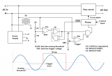
Attached, is the circuit I'm playing with right now. It isn't a schematic, in the classic sense of the word, but more a blending of a schematic and block diagram. (A schemock?) It's just something I use to help me visualize what I'm doing and thinking. It's actually fairly refined from where it started, and it's not as convulted as it might appear. (Maybe.) Beside the Picaxe, there are only three IC's. A dual comparator, and two of the Little Logic series of chips.
At idle, with no control input on the Picaxe, "reset" is held low. Anytime the voltage is above the "trigger" level, U1b will be high. But since the other input of U3 is low, nothing happens. When the voltage drops below the arming threshold, U1a goes high. Again, nothing happens because of U3. U1a and U1b flop back and forth, doing nothing, as long as there is no control input. When the Picaxe gets a control input, it takes the reset line high. Now, when the voltage drops below the arming threshold, U1a goes high. U2's OR gate feeds back into itself via it's sister AND gate and latches itself on. Now, as the voltage rises to the trigger level, U1b goes high, and the pulse is seen at the input of the Picaxe. The Picaxe immediately takes the reset line low again, and sends a 12ms pulse out to the TRIAC circuit. 12ms is approximately 75% of a 60-cycle wavelength, so it holds the TRIAC triggered long enough to get past the 1st zero-crossing point, and then lets the TRIAC shut itself off at the end of the complete cycle.
If I watch the AC output on a 'scope, I should be able to tweak VR1 to compensate for my total propagation delay, to get a perfect zero-crossing point. If everything works as planned, and with proper programming of the Picaxe, I should be able to select any number, and sequence, of individual zero-perfect cycles, from the AC line. In theory.
Artie
Let me explain better what I'm trying to accomplish. This project is multifaceted. Primarily, I want to experiment with dimming and flashing some of the cool new LED light fixtures that are available now. Perhaps even leading to a 21st century version of the cheesey old Realistic light organ. (Just for the fun of it.) I've also wanted to experiment with Ti's "Little Logic" family of IC's ever since I've discovered them, and I've been playing with the Picaxe series of micro-controllers. And lastly, I just enjoy playing with electronics.
Attached, is the circuit I'm playing with right now. It isn't a schematic, in the classic sense of the word, but more a blending of a schematic and block diagram. (A schemock?) It's just something I use to help me visualize what I'm doing and thinking. It's actually fairly refined from where it started, and it's not as convulted as it might appear. (Maybe.) Beside the Picaxe, there are only three IC's. A dual comparator, and two of the Little Logic series of chips.
At idle, with no control input on the Picaxe, "reset" is held low. Anytime the voltage is above the "trigger" level, U1b will be high. But since the other input of U3 is low, nothing happens. When the voltage drops below the arming threshold, U1a goes high. Again, nothing happens because of U3. U1a and U1b flop back and forth, doing nothing, as long as there is no control input. When the Picaxe gets a control input, it takes the reset line high. Now, when the voltage drops below the arming threshold, U1a goes high. U2's OR gate feeds back into itself via it's sister AND gate and latches itself on. Now, as the voltage rises to the trigger level, U1b goes high, and the pulse is seen at the input of the Picaxe. The Picaxe immediately takes the reset line low again, and sends a 12ms pulse out to the TRIAC circuit. 12ms is approximately 75% of a 60-cycle wavelength, so it holds the TRIAC triggered long enough to get past the 1st zero-crossing point, and then lets the TRIAC shut itself off at the end of the complete cycle.
If I watch the AC output on a 'scope, I should be able to tweak VR1 to compensate for my total propagation delay, to get a perfect zero-crossing point. If everything works as planned, and with proper programming of the Picaxe, I should be able to select any number, and sequence, of individual zero-perfect cycles, from the AC line. In theory.
Artie
Attachments
I don't think you need all that glue logic. Most PIC controllers have an ADC to sense threshold, and simple software can replace the hardware logic.
To get the pos going transition, just put the mains AC into any opamp open loop and the opamp output into a PIC logic input through a high value resistor to limit the current as the input goes above Vcc. Then again simple internal software routine to sense the moment the transition occurs. You can get fancy using interrupts if you feel like it.
I've done this for a mains sequencer, very easy and no need for extra hardware.
Jan
Hi,
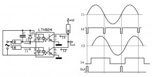
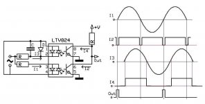
If you use my schematic using a bridge instead one diode it will give you a pulse every time the AC crossed the zero. Also you do not need the adc you just need a digital output to enable whatever your are going to use for the control of the AC. You can use the pulse to trigger a interrupt to control the output. Also my advice instead using the Picaxe why not use an Arduino. It will give you more flexibility. Just an advice. I used my schematic to ramp the AC up/down to control the amplifier power ON/OFF.
If you use my schematic using a bridge instead one diode it will give you a pulse every time the AC crossed the zero. Also you do not need the adc you just need a digital output to enable whatever your are going to use for the control of the AC. You can use the pulse to trigger a interrupt to control the output. Also my advice instead using the Picaxe why not use an Arduino. It will give you more flexibility. Just an advice. I used my schematic to ramp the AC up/down to control the amplifier power ON/OFF.
Hi,
If you use my schematic using a bridge instead one diode it will give you a pulse every time the AC crossed the zero.
The thing is, I only want a pulse when it crosses going neg-to-pos. Not every time. Also, I need a "pre-trigger" so to speak. I want to gate my TRIAC at exactly the zero point. I need to eliminate all propagation delay. Even that that comes from the programming.
Also my advice instead using the Picaxe why not use an Arduino. It will give you more flexibility.
I want to keep it somewhat simple. My own schemock not withstanding.
The smallest 8-pin Picaxe does what I need.
That will not workI want to gate my TRIAC at exactly the zero point. I need to eliminate all propagation delay. Even that that comes from the programming.
A triac needs a minimum of holding current, not there at zero crossing, to conduct.
It needs a gate current past the zero crossing to get enough holding current.So if you are a little bit late that's ok.
Mona
That will not work
A triac needs a minimum of holding current, not there at zero crossing, to conduct.
It needs a gate current past the zero crossing to get enough holding current.So if you are a little bit late that's ok.
Mona
Agree. As long as you keep up de gate current the holdiong current is not really needed. But a triac takes a huge long time to fire anyway, compared to say a few uSec of controller processing. That's no problem.
If you really want to do it fancy, start a counter at a detected zero crossing and fire the triac just a mSec *before* the next zero xing so it fires at the right time. Again, a no-brainer in software
Jan
> bone up on my TRIAC theory
A Triac is two SCRs.
An SCR is two transistors.
If you trigger the gate at ZERO current in the transistors, they have zero gain, they won't won't turn each other on, nothing happens.
FWIW, zero voltage may not be zero current. Yes for a resistor, no for any significant reactance, and ?? for electronic gizmos like LEDs with built-in power circuits.
Why do you think you need zero-cross? I know it means less hash, but is rarely essential. Especially for a blinky-light box.
If you really want to do it fancy, start a counter at a detected zero crossing and fire the triac just a mSec *before* the next zero xing so it fires at the right time. Again, a no-brainer in software
Jan
I like that idea. I'll "doodle up" a couple things along those lines.
Why do you think you need zero-cross? I know it means less hash, but is rarely essential. Especially for a blinky-light box.
Partially for "neatness". Partially, just to see if I can do it. But mostly, because I was under the impression that triggering at the zero point generated less buzz and RF. This will be used in a small home studio with instruments and audio equipment. I should probably experiment with a store bought, off-the-wall dimmer, before I get carried away.
But remember, part of this is just for the fun of experimenting with an idea.
I like that idea. I'll "doodle up" a couple things along those lines.
Partially for "neatness". Partially, just to see if I can do it. But mostly, because I was under the impression that triggering at the zero point generated less buzz and RF. This will be used in a small home studio with instruments and audio equipment. I should probably experiment with a store bought, off-the-wall dimmer, before I get carried away.
But remember, part of this is just for the fun of experimenting with an idea.
It is actually more important to do the switch on at the same point as you switched it off. That leaves the transformer in a magnetized state that will cause almost no inrush when switched on at the same point on the wave next time.
All sooo simple in software
Jan
- Status
- This old topic is closed. If you want to reopen this topic, contact a moderator using the "Report Post" button.
- Home
- Amplifiers
- Power Supplies
- Positive sensing zero-crossing detector.