Mark, I'm not sure if you are still subscribed to the Groner preamp thread so I will post here as well. There is indeed a problem with the test setup. I tested an LM317. 0.1uF cap at input, 115R and 1kR voltage divider to set the output to 12V, 10uF cap on the adjust pin, 0.1uF on the output followed by a 220uF electrolytic. As with the other tests, attached to the output of the LM317 are two 10W 12R resistors in series generating a load of 0.5A.
I've used a short piece of shielded coax cable to connect the output of the LM317 to the input of the preamp. (Shield to ground, inner wire to +ve.)
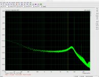
Attached is a screen grab of ARTA's spectrum analyser while injecting a 20kHz 1Vpp ripple riding on 18V DC into the LM317. PSRR readings:
Hz dBV
50 -65
100 -71.8
500 -96
1k -94.5
2k -93.4
3k -90.5
5k -86.7
10k -78.5
20k -70.7
30k -75.3
40k -76.0
50k -76.1
60k -76.3
70k -75.4
80k -76.0
90k -74.6
I have to believe this is some sort of interaction with the preamp. I have tested the frequency response of the preamp on its own by injecting stimuli from my signal generator into it (with the assistance of a voltage divider) and it would appear to measure flat.
EDIT: I guess with the LM317 I could couple the output to my sound card without the preamp via a couple of bipolar caps...
I've used a short piece of shielded coax cable to connect the output of the LM317 to the input of the preamp. (Shield to ground, inner wire to +ve.)
Attached is a screen grab of ARTA's spectrum analyser while injecting a 20kHz 1Vpp ripple riding on 18V DC into the LM317. PSRR readings:
Hz dBV
50 -65
100 -71.8
500 -96
1k -94.5
2k -93.4
3k -90.5
5k -86.7
10k -78.5
20k -70.7
30k -75.3
40k -76.0
50k -76.1
60k -76.3
70k -75.4
80k -76.0
90k -74.6
I have to believe this is some sort of interaction with the preamp. I have tested the frequency response of the preamp on its own by injecting stimuli from my signal generator into it (with the assistance of a voltage divider) and it would appear to measure flat.
EDIT: I guess with the LM317 I could couple the output to my sound card without the preamp via a couple of bipolar caps...
Attachments
Last edited:
Yikes!
I suppose a 1000-to-1 resistive voltage divider (instead of a voltage regulator PCB) would be expected to exhibit 60dB of attenuation at all frequencies. Does reality match expectations? Or is there a surprise?
I suppose you could then connect a capacitor from junction node to ground in the above resistive voltage divider, and thereby get MORE attenuation above the corner frequency (with slope 20dB/decade). But: is that what happens?
Maybe a way to begin to understand the measurement apparatus' behavior on hard problems, is to first understand its behavior on easy problems.
Good suggestion (with the load reduced significantly). I did something similar using my signal generator and a resistive voltage divider (link) into the preamp but that test of course excluded the rail driver. It seemed to work fine. I think I might try bypassing the preamp with the LM317 and see how that looks (EDIT above). I should have enough resolution.
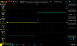
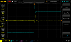
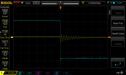
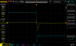
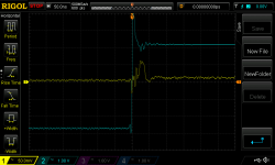
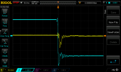
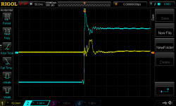
I was packing away my test board and remembered that previously I had wanted to test a much more aggressive op amp with it - just for fun. I quickly soldered an AD797 in place of the AD817 and connected Mark's chop-chop box and scope. The results were interesting.
At first, I made not other changes to the board. The first few measurements showed unexpected promise (first 3 pics) but an examination of the other side of the stepped waveform (pic 4) indicated that, while stable, the circuit was underdamped. Actually, I was expecting much worse.
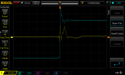
I grabbed a 20p cap and soldered it into the "Cy" compensation cap placeholder on the board. Et voila, damped a lot better. Last two pics.
I have not tried a smaller compensation cap. (I have 5p, 10p and 15p in stock.)
Given the far greater loop gain of the AD797 it should lead to a good improvement in line rejection over the AD817 circuit.
At first, I made not other changes to the board. The first few measurements showed unexpected promise (first 3 pics) but an examination of the other side of the stepped waveform (pic 4) indicated that, while stable, the circuit was underdamped. Actually, I was expecting much worse.
I grabbed a 20p cap and soldered it into the "Cy" compensation cap placeholder on the board. Et voila, damped a lot better. Last two pics.
I have not tried a smaller compensation cap. (I have 5p, 10p and 15p in stock.)
Given the far greater loop gain of the AD797 it should lead to a good improvement in line rejection over the AD817 circuit.
Attachments
Yep. 2.8MHZ from model. Only 40 degrees of phase margin with no Ccomp.
I might try a smaller compensation cap as simulation suggests only a pF or so is necessary for good phase margin.
I am using the D44VH10 model for the pass transistor. When I drop in the 2SC6144SG model I get nonsense...
I might try a smaller compensation cap as simulation suggests only a pF or so is necessary for good phase margin.
I am using the D44VH10 model for the pass transistor. When I drop in the 2SC6144SG model I get nonsense...
reducing Ccomp to 5p from 15p shows some possible under-damping - hard to tell
Modelled line rejection is rather crushed by a compensation cap, but I think this would need to be empirically tested. Given I was using my headphone amp enclosure for my line rejection tests and this is now put back together and in use, any attempts by me to measure this will have to wait for some time.
Modelled line rejection is rather crushed by a compensation cap, but I think this would need to be empirically tested. Given I was using my headphone amp enclosure for my line rejection tests and this is now put back together and in use, any attempts by me to measure this will have to wait for some time.
Attachments
- Status
- This old topic is closed. If you want to reopen this topic, contact a moderator using the "Report Post" button.
- Home
- Amplifiers
- Power Supplies
- Thermal considerations for Fairchild SDIP bridge rectifiers