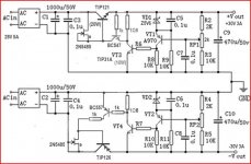
Could anyone shed light on this topology? I cannot find any examples close to it in the sheets.
VT3 and VT4 are high current transistors, yet collector and emitter are connected across POS and NEG.

I was pondering a regulated PS for a 100W Class AB, and came across this on eBay cheap. LM317 will not cut the mustard, but the bare board is worth the price.
I have also been informed "nobody" regulates the DC output power.
Any comment appreciated.
Thanks.
VT3 and VT4 are high current transistors, yet collector and emitter are connected across POS and NEG.
I was pondering a regulated PS for a 100W Class AB, and came across this on eBay cheap. LM317 will not cut the mustard, but the bare board is worth the price.
I have also been informed "nobody" regulates the DC output power.
Any comment appreciated.
Thanks.
Shunt regulator.
Instead of an LM317, use a DN2540 depletion MOSFET, besides LM317 is a bit noisy.
Here's a better implementation from Walt Jung: http://www.waltjung.org/PDFs/UnivReg_122714.pdf
There isn't much point in regulating the rails of an output stage for a 100W AB amplifier. You're just needlessly burning watts which could be converted to music.
VT3 and VT4 collector & emitter are also connected across the LM317 Adj pin and Gnd. So their purpose is to act as variable resistors. I see the "coarse" voltage set controlled by the value of zener diodes VD1 and VD2, and the "fine" voltage set controlled by potentiometers RP1 and RP2.Could anyone shed light on this topology? I cannot find any examples close to it in the sheets.
VT3 and VT4 are high current transistors, yet collector and emitter are connected across POS and NEG.
Thank you gentlemen. The need is probably not that critical. In the case of a musical instrument amplifier, mains in say, Northeast USA, could vary between 105-125VAC depending on a specific location. If such a swing took place, the change in output amplitude would be noticeable. I am thinking primarily for an electric guitar played with active feedback through the speakers. It could conceivably ruin a performance. It would also affect practice sessions since they would not be controlled. Sometimes the intended effect will be achieved, and sometimes not. We all have seen players reach for the amp and effect controls live. I could be voltage changes, acoustics, or even their mental state at the time.
I see the wasted energy now since a 100mA needs heatsinks. What would 3A on each rail require? Water cooling?
I have seen extremely large capacity capacitor banks, the size of a folded checker board and enough for a spot welder. I wonder why one would need so much capacity. The only think I can think of is softening any change in mains supply to the point it is not that noticeable.
For reference, here is a board that is close to the Jung Universal Shunt Regulator 2015 DIY Kit 63117 A Low Noise Dual Output V Shunt Regulator with Soft Start | eBay
Why not try a tandem regulator ? That is a shunt and a current source that follows the current demand.
Something like this
Mona
Thank you sir. But if there is not a board already made I will not do it. I also do not understand current sources, but it sounds efficient since something changes according the current draw, which would vary in this application, which usually passes 1A most of the time.
I was looking at a LM317 implementations using multiple pass transistors to reduce switching resistance and thus wasted heat. With this strategy, I may use cheap, ubiquitous 3-term regulator board(s), and just have to make a simple, separate pass transistor board with the load sharing resistors.

or

Thank you sir. But if there is not a board already made I will not do it. I also do not understand current sources, but it sounds efficient since something changes according the current draw, which would vary in this application, which usually passes 1A most of the time.
I was looking at a LM317 implementations using multiple pass transistors to reduce switching resistance and thus wasted heat. With this strategy, I may use cheap, ubiquitous 3-term regulator board(s), and just have to make a simple, separate pass transistor board with the load sharing resistors.
View attachment 496741
or
View attachment 496742
Time and Time again recently I have warned that these configurations of LM317 and series pass transistors Do Not work very good and have very bad load regulation.
It has also been known to cause destruction of the output devices by over voltage on the base of the transistors when a large is current is drawn from the circuit.
I have tested this and the biggest flaw is that there is no negative feedback for the LM317 to compensate for changing conditions of the output load.
Please See this post for links to several threads concerning this matter,
http://www.diyaudio.com/forums/ever...rs-keep-blowing-power-supply.html#post4396045
FWIW
Cheers!!
jer
")
Thank you jer. I had a suspicion they were no good, based on common sense rather than EE.
It appears no one has made one because there is virtually no demand for it in audio.
Obviously, a SMPS would be the way to go, but subsequent filtering is required due to ripple, and I can imagine what the RFI emissions would be like from the transistors and the magnetic field from the inductors.
In a high-gain guitar amp I don't think it will work, unless they are mounted 10ft. away. Perhaps there would be hope if they were mounted on top of the chassis, and double-shielded.
Perhaps an optocoupler circuit could be designed that varies the input signal in proportion to the available DC rail voltage.
Last edited:
No, gain is quite independent of supply voltage unless you go into clipping.mains in say, Northeast USA, could vary between 105-125VAC depending on a specific location. If such a swing took place, the change in output amplitude would be noticeable.
No, gain is quite independent of supply voltage unless you go into clipping.
True, but I meant the output to the drivers.
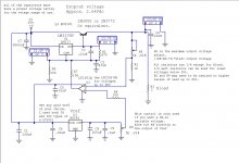
How about a circuit around the good old UA723?....
Thank you for this idea. This seems reasonable. It looks like the floating scheme is necessary since the output voltage needs to be >40V.
Only a few more resistors and a stud-mounted zener diode NTE5204A (for the 1N1826) which has to be isolated from the the single pass transistor--also stud mounted.
There's nothing to be said of the switching frequency or the efficiency--but app notes and other commentaries must be extant. The whole contraption would have to go outside the chassis anyway.
Back to the optoisolator circuit. The power amp is already buffered with an opamp or buffer. It is not a problem to create a divider for the addition of a voltage-controlled resistor like the TLP4006 on one of the resistors. It would neither cause distortion, noise, nor would it cause the power amp to oscillate, and everything goes inside the chassis. The ratio would have to be hammered out, but the range is minimal, and a small capacitor can slow the rate of change on the emitter side. There is already a 12VDC control PS in the system.
I will build the machine with that contingency, and test to see to what extent a ~15% reduction in mains voltage does to the amp output. Then size the resistors and damping cap accordingly. Probably a better test would be to reduce the mains voltage while actually playing the instrument under a host of scenarios, as it may be found it all doesn't matter.
Time and Time again recently I have warned that these configurations of LM317 and series pass transistors Do Not work very good and have very bad load regulation....jer
How about this one?

Interesting I did try a resistor connected much like the 1k and it improved things a little bit.
But I wasn't satisfied with the performance yet but I didn't have a transistor stage either.
It was basically connect to the point at the bottom of the 75 ohm resistor in that schematic but without the transistor.
So I broke down and added an opamp (like the function of the transistor) and it is super stable and rock solid!!
The voltage does not fluctuate when I draw an intermittent load of 3.5amp to 0 amps (on,off,on,off,on,off.......) from the circuit at all.
The only other thing about my circuit and probably that one too, is that it will not go completely to 0volts if it were adjustable.
This is typical of these regulators, and to do so I need a negative voltage on my opamp to bring the LM317 ground reference to a -V below ground.
I only had one winding to work with and it is not center taped and using a doubler produced to much voltage for the opamp I used so I am going to get a TC7660 charge pump to produce the -2 to -5v needed for my circuit and then I will be able to have a true 0v adjustment setting.
For reference here is my Final circuit,
http://www.diyaudio.com/forums/chip-amps/261125-lm3886-problem.html#post4064510
On quiet days have measured the noise from the circuit to be as low as 30uv to 100uv Peak to Peak even when drawing 3.5 amps form it!!
jer
Attachments
Last edited:
....For reference here is my Final circuit,....jer
When will the boards be available? Will they be all POS or POS/NEG?
Here is a board to start with:

eBay link: LM317 LM337 Dual Rail Servo Regulator Power Supply DC Adjustable 5V 35V | eBay
The VREF and pass transistor would have to be on a separate board; simple at least. Perhaps VREF could be squeezed in on the servo board with some drilling and jumpers.
Here is "Jims" High Current Regulator, which comes as a kit with 30V max out, but I suppose it could be modified for 50V. No opamp or VREF, though.

eBay link: High Current Dual Rail Regulator Kit for Power Amplifier or Bench Power Supply | eBay
eBay link: LM317 LM337 Dual Rail Servo Regulator Power Supply DC Adjustable 5V 35V | eBay
The VREF and pass transistor would have to be on a separate board; simple at least. Perhaps VREF could be squeezed in on the servo board with some drilling and jumpers.
Here is "Jims" High Current Regulator, which comes as a kit with 30V max out, but I suppose it could be modified for 50V. No opamp or VREF, though.
eBay link: High Current Dual Rail Regulator Kit for Power Amplifier or Bench Power Supply | eBay
Last edited:
I ran that circuit in a LT spice and it hasn't that great either, however I did build my own version similar to it and it work okay but the load regulation was to poor too.
I can provide you with the Circuit Maker file if you have Cm and Traxmaker.
I just made mine on a small breadboard and piggybacked it to the existing board I was working with.
I had thought about a negative voltage version but I don't have any suitable PNP power transistors to work with.
For something like that I would just use two of them isolated and tie them in series.
LT devices are great and they are easy to parallel and the do have equivalent negative versions available as well.
When I do start work again on the higher current versions I will gladly work out the board patterns and present them.
Currently I am still slowly working on a PIC controller for the supply and I just got some 7-segment display's that I'd like to maybe use for it, and also use a USB interface to display its functions on a PC as well all from a single tiny PIC chip.
jer
Attachments
Last edited:
I ran that circuit in a LT spice and it hasn't that great either, however I did build my own version similar to it and it work okay but the load regulation was to poor too....
I can provide you with the Circuit Maker file if you have Cm and Traxmaker....jer
Thanks. I would like to take a look. My email is open.
Why can't MOSFETS be utilized with the "0" gate current and low RDSon?
How poor is the regulation in "Jims" implementation?
It had to do with the value of the resistors around the transistors.
As you drew more current the voltage drop across them increased as well.
At rather high currents these resistors needed to have a rather large power dissipation.
And if the values were to high it would limit the current and drop the voltage at the same time.
The lower the values then the transistors wouldn't turn on allow for proper regulation of the voltage as well when it was set to a certain level.
How ever it did work better than the other version that is susceptible to blowing output devices.
Just build it in LTspice and you will see what I am talking about.
I am not sure if I still have that ASC but I will look and see if I do.
I didn't quite completely grasp the concept of the design since I didn't study it long enough.
I found that it was to costly to have all of those resistors and have poor performance too.
When adding a simple opamp was all that was needed.
MOSFET's can be used quite easily, in fact very first the version I made used a LM317 for the voltage control and I used it to feed an IRF512 FET that fed the base's of four paralleled 2N3055's.
It was very similar to that very same configuration.
I worked on it for days in CM until I got it to work and then I built it.
It was my very First simulated designed in CM and then built circuit, sadly I had lost the CM file since then from 2001.
In a comparison of CM and the real circuit, CM was pretty darn accurate back in the day.
I used a 450watt UPS transformer that I had, and I got 30amps out of it at 15v and I could get as much as 50 amps when it was loaded so hard it could only produce 9V.
I had made a 30 step baragraph display so that I could monitor the output voltage in real time at .5v per step.
jer
P.S. I will look for those Files and post them here for all to see if I still have them.
Last edited:
- Status
- This old topic is closed. If you want to reopen this topic, contact a moderator using the "Report Post" button.
- Home
- Amplifiers
- Power Supplies
- LM317 + 2 Transistors "Class A" Regulator?