I've cut a pair of wires long enough to accommodate all the connections/spans and used a hand drill to do the twisting. Either tie a knot on one end and hook it to a nail, or use a vice. There can be some relaxing of the twist but you can account for that. Then cut or strip segments to desired length.
way overkill bu
nice setup but imho a bit over kill there dont you think!? ..
..
nice setup but imho a bit over kill there dont you think!?
..Hi
Hopefully this little project by a novice is worthy of your attention and assistance!
I have assembled an audio server made up with an ASRock Z87E-ITX mobo, Haswell 4570T processor, ESI Juli@ XTe sound card with clocks upgraded with a Fidelity Audio Micro Clock 2 and PicoPSU power supply with 12V 'brick'.
In the interest of achieving a better power supply and learning more about electronics I have been upgrading the power supply. As a first step, and with a lot of kind assistance from Brent of Fidelity Audio here in the UK, I assembled with point-to-point wiring a 12V 'rail' comprising two 22,000uF Fidelity Audio 'SI' caps, an SPower HC 12v regulator and another 22,000uF 'SI' capacitor, fed 18V from another 'brick'. The caps and regulator may well be overkill for this application but it seems to work very well. This 12V powers the PicoPSU and the Micro Clock 2.
I'm interested in taking this a step or two further. One direction, although it may not be the first one that I implement, is to replace the brick with a 160VA toroidal transformer with 15V secondaries and a full-wave bridge rectifier made from four Cree C3D08060A Silicon Carbide Schottky diodes. 160VA may well be more than enough but it fits.
The second direction involves what I believe is a CLC filter. Specifically, it has been suggested to me that my existing setup could be improved further by adding a series of film capacitors and a choke ahead of the 'SI' caps:
Input
Wima MKP10 0.47uF 1600V
Wima MKP10 0.047uF 1000V
Wima MKP10 4700pF 1000V
Coilcraft CMT4 26mH 6A 0.115Ohm
Existing caps...etc
I picked up these parts (I got the choke cheekily as a request for sample and the Wima caps were essentially free as they tipped my Mouser order into free delivery) but as I read a bit more about CLC filters I'm unsure that these cap values are appropriate for this application or indeed whether the filter adds anything beyond the existing cap/regulator setup. (The choke is, ahem, huge but can be made to fit.)
I'd therefore like to start by asking for thoughts on the filter, both with respect to adding it into my existing 'brick' setup and with respect to the transformer/rectifier setup.
I'm sure I will have questions on the transformer/rectifier as well at some point.
Thanks in advance
Steve
Well i am pleased to say it all powered up and I didn't electrocute myself!
At the moment I don't have the snubber installed and I left the wiring "as is" just to see if it all worked. I have the caps for the snubber but I have taken one of Mark's Quasimodo "kits" as a project in and of itself and will determine the appropriate resistor with that and then install the snubber.
Right now, I'm going to sit back and listen to some music! Thanks for all the help - and patience - thus far guys.
You will get a much better grasp of how to design a linear PSU if you buy or borrow a copy of 'The Art of Electronics' by Paul Horowitz and Winfield Hill, which you will also find useful in many other areas. It is widely regarded as probably the best introduction to general electronic design available, and it will fill in many of the inevitable lacunae in your knowledge.
I just wanted to thank you for the reference. I got the book. So far I've had to read the opening chapter about 10 times! At least I know what I am getting myself into.
Thanks
A very basic question:
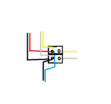
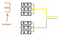
I have a few wire pairs running off this 12V rail now (to Fidelity Audio clock for my ESI Juli@ XTe, to the PicoPSU, to my 5V regulator for the SSD). It's a bit of a mess of wires all attached to the output cap. I'm wondering if there is a suitable terminal block that I could use with a single pair in and multiple pairs out which can be attached to the bottom of my enclosure. There just seems to be a bewildering array of terminal blocks and while I have been wading through them perhaps someone can point me in a direction which would narrow the search. TIA.
I have a few wire pairs running off this 12V rail now (to Fidelity Audio clock for my ESI Juli@ XTe, to the PicoPSU, to my 5V regulator for the SSD). It's a bit of a mess of wires all attached to the output cap. I'm wondering if there is a suitable terminal block that I could use with a single pair in and multiple pairs out which can be attached to the bottom of my enclosure. There just seems to be a bewildering array of terminal blocks and while I have been wading through them perhaps someone can point me in a direction which would narrow the search. TIA.
If you took Andrew's suggestion on twisting, I don't see much more that could be done without relocating the components. A full chassis top shot may suggest an alternate arrangement, but if you are not having a hum or other problem I'm not sure of the need to make any changes. I'm a big fan of keeping all wires as short as possible, but sometimes a bit more length can enhance layout and aesthetic considerations. LOOK HERE
Last edited:
So stick with hard soldering all the component wiring runs to the final output cap (as opposed to some sort of terminal block)? I guess I can handle redoing all the work if I need to change something - it's just a bit annoying as all the wires are stacked on top of each other at the pins of the output cap.
Would still like to see a full photo showing all components in the build - when you get a chance.
Hi Bob
Well, better late than never. I finally took a pick as I dropped in a few new parts.
An externally hosted image should be here but it was not working when we last tested it.
You can see the cluster of power leads off the output cap.
Regards
Steve
Very impressive! If your concern was simplifying the wiring and/or adding a centralized terminal block, I can't see the need. If you wanted to use a PCB style cap bank that could influence things somewhat. But I actually like the P2P elements as you have incorporated them. A simple Euro Style screw block would work but it's essentially the same as you have now with some added convince to avoid soldering . The experts may have further suggestions.
Don't know if I mentioned - but I started a system quite similar to yours. Sadly the Pico didn't have enough power to even boot the Asus board I have. Glad you were able to get yours completed.
Don't know if I mentioned - but I started a system quite similar to yours. Sadly the Pico didn't have enough power to even boot the Asus board I have. Glad you were able to get yours completed.
Attachments
Last edited:
Thanks. I guess I could use something like the block you show. I used one for the secondaries of the transformer. However I was thinking of something with two inputs and multiple outputs rather than stuffing all the outputs into two holes.
Completed is a relative term with this stuff. Today I added the Corcom power entry filter and the DC regulator powering the SSD. Next up is to take 12v from my PSU for the 4 pin 12v to the board rather than the cable from the picoPSU. Then ultimately a full linear ATX PSU. After that, a new enclosure and then....
I'm surprised you had issues with your mobo and the picoPSU. Obviouslythe mobo doesn't need much power and the picoPSU should manage the power good sequencing.
- Status
- This old topic is closed. If you want to reopen this topic, contact a moderator using the "Report Post" button.
- Home
- Amplifiers
- Power Supplies
- Help a novice steadily build a linear 12V power supply?