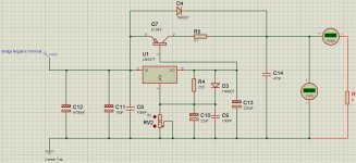
Hi all, i put together a regulated split power supply based on lm317/lm337 regulators. To increase the output current i used a pass transistors 2sc5200/2sa4943. What i would like to really know is your take on the capacitance, its quantities and placement. The power supply will be used to power a chip amp (TDA's). In the attachments the negative part of the supply.
I am really sorry if the question seems redundant or been repeatedly asked before but the amount of information and debate on this subject (Capacitance) is huge and i am actually quite confused.")
I am really sorry if the question seems redundant or been repeatedly asked before but the amount of information and debate on this subject (Capacitance) is huge and i am actually quite confused.
Attachments
What sort of output voltage and current are you looking at ?
As long as the maximum ripple at the input of the regulator keeps the Vin/Vout criteria for the regulator there is no need to increase the input cap.
The transformer is 24-0-24 480 VA and the required output level with minimal ripple is 30v @ 5A. Thanks for your input.
If you are using a full wave bridge at 48V the rectified voltage will be 67 volts or so. If the regulator is only expected to output 30V you could have over 30V of ripple before the output sees the ripple.
However, the regulator is going to get VERY HOT with Vin/Vout of 30V at 5A, it's going to be dissipating some 150W or so.
However, the regulator is going to get VERY HOT with Vin/Vout of 30V at 5A, it's going to be dissipating some 150W or so.
If you are using a full wave bridge at 48V the rectified voltage will be 67 volts or so. If the regulator is only expected to output 30V you could have over 30V of ripple before the output sees the ripple.
However, the regulator is going to get VERY HOT with Vin/Vout of 30V at 5A, it's going to be dissipating some 150W or so.
Sorry i didn't make myself clear. I am using a full wave bridge and the center tap as a ground to power a split supply (lm317 for the positive part and lm337 for the negative).
In which case the transformer isn't providing enough headroom for a regulated supply.
Have a check of the datasheet for the LM317/LM337 and then add the Vbe for the pass transistor. Vin/Vout usually needs to be in the order of 3V minimum. normally more.
With such a close margin you would need HUGE caps to prevent regulator sag, ie when the regulator can't regulate because Vi/Vout is too low.
Might as well do without the regulator altogether and just use a nice bunch of caps.
Last edited:
Your circuit has errors and will not work as intended. Have you tried simulating it?
Your boost transistor (Q7) is all wrong. At best, it is backwards - the emitter must be facing the other way - but actually I think it should be an NPN type not PNP. PNP would be used in this way on the positive side. You could use a PNP on the negative side (with the emitter on the load side as I said) but you need a different arrangement probably with another transistor driving it besides the LM337.
What is the 0.1 Ω resistor doing other than dissipating heat and ruining the load regulation? You have mis-connected some things on the output side of the LM337.
Try a google image search for something like LM337 high current or LM337 transistor, and you will find plenty of working examples of what you tried to do here.
On final note is that it is customary to draw a negative supply with the ground at the top. This makes it easy to draw underneath a corresponding positive supply, and it keeps the higher voltages at the top of the page, and load current flowing in the general downward and clockwise direction. This helps to prevent mistakes like the PNP/NPN transistor and/or emitter/collector flip. Intuitively knowing and seeing the direction of current flow means you will easily spot the emitter arrow pointing the wrong direction. In both ON Semi and TI datasheets, all of the example circuits are drawn this way whether or not a positive regulator is also shown.
Last edited:
Have a check of the datasheet for the LM317/LM337 and then add the Vbe for the pass transistor. Vin/Vout usually needs to be in the order of 3V minimum. normally more.
Sorry i didn't understand the Vbe part
I haven't even started to look at the circuit, I'm just addressing the pre-reg voltages.
The LM317/LM337 will need a minimum Vin to Vout in order to be able to function. The pass transistor also needs a small voltage Vbe (which is about 0.7V) to operate, this needs to be added to the Vin/Vout of the regulator IC. To operate regulators so close to their minimum limits is foolhardy and destined for failure.
Do have a good read of the LM317/ 337 datasheet as you have got the +ve and -ve pass circuits mixed up.
Last edited:
Just saw the notes about voltages, and I agree with Katieanddad about the headroom. You need more than 33 or 34 V at the input if you want to have 30 V @5 A at the output. Generally more headroom is required when using a transistor boosted circuit. You will likely need to reduce the output to something like 27 V or get a different transformer.
Another option may be to use low dropout regulators. But you would need to use a few in parallel, and I don't know how well they behave like that (LDO regulators are tempermental at the best of times).
Another option may be to use low dropout regulators. But you would need to use a few in parallel, and I don't know how well they behave like that (LDO regulators are tempermental at the best of times).
Your circuit has errors and will not work as intended. Have you tried simulating it?
Yes i did and it worked quite fine actually.
You have mis-connected some things on the output side of the LM337.
Like what exactly?
Try a google image search for something like LM337 high current or LM337 transistor, and you will find plenty of working examples of what you tried to do here.
Did that but all i can find was the lm317 circuit or the positive half of the power supply.
Sorry i didn't understand the Vbe part
VBE is Voltage across the base-emitter junction of the transistor (Q7 in your schematic). You will need to find what VBE should be at 5 A output current (a.k.a. IC) by examining the datasheet for the 2SA1943. (Hint: Toshiba datasheet, page 3, "IC - VBE" graph).
You will likely need to reduce the output to something like 27 V or get a different transformer.
I can do just fine with +-25 to +-27 voltage output at 5A.
Did that but all i can find was the lm317 circuit or the positive half of the power supply.
Try googling:
lm337 high current site:electronics-diy.com
VBE is Voltage across the base-emitter junction of the transistor (Q7 in your schematic). You will need to find what VBE should be at 5 A output current (a.k.a. IC) by examining the datasheet for the 2SA1943. (Hint: Toshiba datasheet, page 3, "IC - VBE" graph).
Measuring the voltage between the base and emitter in the simulated circuit gives -0.99V.
Unfortunately, simulations often don't find common mistakes like flipping the emitter and collector. Plenty of simulated transistors work very well backwards. Most real BJT transistors work to some extent backwards, but not well.
Fortunately they do.
Try googling:
lm337 high current site:electronics-diy.com
Thanks for the pointer, but can the 3055/2955 be swapped with the Sanken pair. And also what about the capacitors arrangement and values.
- Status
- This old topic is closed. If you want to reopen this topic, contact a moderator using the "Report Post" button.
- Home
- Amplifiers
- Power Supplies
- Regulated Negative Power Supply