LM317 has a noise of 0.03% of the output voltage. No need for measuring.
I would suggest using a TL431 with a series pass transistor instead of the LM317 since you are looking for reducing the noise.
Gajanan Phadte
So if the line regulation of the lm317 is 0.03% what is the line regulation for the tl431? The OnSemi datasheet says that the voltage reference tolerance is +-0.4% @25C. Are you really sure that the output performance of the lm317 cannot be improved? (Hint: think of Jung 2000 and Teddyreg super regulators)
Edit: and of course YARPS power supply.
Last edited:
In the link i posted there are some measured proof of the effect of a capacitor multiplier prior to the regulator on the output ripple, what measurements or theory do you have to back up your claim?
Best regards.
I really think you are not quite doing your basic homework mate, which BTW first off is reading the 317 brochure. Then you may understand what and why you have been suggested regarding this implementation.
On one hand you ask for basic advice, but you do it in kinda aggressive way.
You have to remember you are only receiving advice. Me nor anyone has to back up the statements. You pick them up for what's worth and do your reseach and experimentation on what calls your attention.
It's you project and whatever floats your boat it's OK to me.
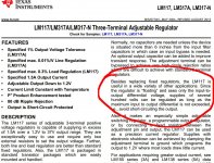
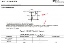
Anyways, below is an extract from the 317 pages showing why you have to take care of the input/output voltage difference at all circumstances, why it has been suggested to you to put some capacitance after the regulator (you already have C3 there in your circuit but I'd suggest you implement some mod since you say you still have noise), and finally how TI floats the 723, which I extrapolated to the 317 with the aid of the transistor (Q2) you already fitted.
Now I think I'll stay off for the rest of this thread. Good luck with the project.
")
Attachments
I really think you are not quite doing your basic homework mate, which BTW first off is reading the 317 brochure. Then you may understand what and why you have been suggested regarding this implementation.
On one hand you ask for basic advice, but you do it in kinda aggressive way.
You have to remember you are only receiving advice. Me nor anyone has to back up the statements. You pick them up for what's worth and do your reseach and experimentation on what calls your attention.
It's you project and whatever floats your boat it's OK to me.
Anyways, below is an extract from the 317 pages showing why you have to take care of the input/output voltage difference at all circumstances, why it has been suggested to you to put some capacitance after the regulator (you already have C3 there in your circuit but I'd suggest you implement some mod since you say you still have noise), and finally how TI floats the 723, which I extrapolated to the 317 with the aid of the transistor (Q2) you already fitted.
Now I think I'll stay off for the rest of this thread. Good luck with the project.
It seems to me the word "homework' is what first comes to mind when someone like you who clearly doesn't know at all what he's talking about, you sir are talking nonsense and shirking the main questions completely due to apparently your lack of knowledge and if you (or anybody else with some sanity) looks at this quite long a thread will find your (and your like) precious contributions a load of steaming bull in every way possible, you suggests the use of a zener diode across the input-output terminals YAY how clever...what about my clear inquiries? you don't touch them at all Why? because you don't know what you're talking about AT ALL, somebody else will suggest scrapping it altogether and put together some resistors and capacitors and call at a day so what exactly is the purpose of the thread if i originally elected to build a ******* regulated supply using a ******* LM317, and of course the great advice of using another regulator which i know about its existence but isn't available to me...again the topic is about using a specific component to do a specific job.
You may want to look at a similar thread a while back...
http://www.diyaudio.com/forums/power-supplies/86495-pass-transistor-regulated-supply.html
and learn something or two from it, the answers is well organized, concise, actually helpful and confined to the main topic, the OP starts with a question and in the same amount of time and effort ends up with a working prototype, how marvelous is that? while THIS thread started with the circuit half finished and ended up with utter rubbish, but i guess times (and people) are quite different ain't it??
I didn't ask for your specific help (or anyone else for that matter) i asked for "SUGGESTIONS" and about "SPECIFIC THINGS" and i got "NONE" so please stay away if you don't know about your business, i posted here to benefit from knowledgeable people opinions and to brain-storm not to brain-fart.
and it's called a "datasheet" not a "brochure" where certain devices parameters and application notes are listed and guess what the lm317 got one on its own which i posted a part of it a few posts ago so no "extrapolation" required certainly not from you.
Last edited:
So if the line regulation of the lm317 is 0.03% what is the line regulation for the tl431?
noise is not equal to line regulation
Bye
Gajanan Phadte
Great answer...so you don't know? and if so why did you suggested it?
- Status
- This old topic is closed. If you want to reopen this topic, contact a moderator using the "Report Post" button.
- Home
- Amplifiers
- Power Supplies
- Regulated Negative Power Supply