I was looking at true RMS converter circuits that give a DC output equivalent to the RMS value of the input voltage. The thought then occurred to me that it would be easy to add such a circuit with a meter to an amplifier displaying the RMS voltage as the music is playing. Of little value but kinda cool.
It would be even cooler if the meter displayed actual Watts being pumped into the speaker. You could measure the voltage, apply some sort of scaling based on an estimate of the speaker impedance and put the numbers on the meter. This has been done too many times and is just a gimmick. What I am thinking about is measuring the actual power, i.e. current multiplied by voltage. Doing this in the analog domain would require a way to measure the RMS current as well and then it would have to be put through an analog multiplier.
This kind of thing is already being done in mains electricity circuits so that you can pay for the energy wasted by say, a 5W SET amplifier. I haven't read up on how this is done yet, but I guess the techniques could be applied to music and loudspeakers. Or could they?
Has any commercial manufacturer ever done this? Or has anybody here ever tried this. A search on this forum yielded a few threads on measuting output power under lab conditions but nothing like what I have described.
PS: I posted this under power supplies because such a circuit could be used in a sand or a glass power amp. This seemed the only section that fits.
I have done it in RF circuits, never audio but audio is easier.
Note that you can get two numbers that mean slightly different things.
1 average (rms (V) * rms (I)) = apparent power in VA.
2 average ( V * I) = real power delivered to the load.
Additionally if you have the sensors installed you can get Z = rms (V)/rms(I), useful somewhat for testing loudspeakers.
The voltage sampling is obvious, and I would advocate one of those broadband hall sensors as being a simple, packaged way to read the load current.
Either stuff the values into a two channel syncronous sampling ADC and do the math in a small micro or use an analogue multiplier to get the job done, whatever works for you (The micro will be less frone to drift), you could even consider one of ADs log amps as a good way to get a wide input range and to simplify the multiplication or division, output will be in dB relative to whatever reference you choose which is nice.
Regards, Dan.
Hi,
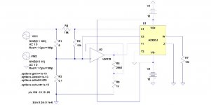
What you are asking can be easily done by using a micro as shown in the attached schematic. The problem it is that people get scared when the micro it is mentioned. To calculate watts you need the current and the voltage output. The current it is read by the ASC712 hall effect current sensors and the voltage is read by the 2 resistor voltage divider. This will bring the voltage down to the micro analog input range. Then the watts calculation it is done in the program and send to the display. Total cost it is $30 dollars. Simple and Nothing to it.
What you are asking can be easily done by using a micro as shown in the attached schematic. The problem it is that people get scared when the micro it is mentioned. To calculate watts you need the current and the voltage output. The current it is read by the ASC712 hall effect current sensors and the voltage is read by the 2 resistor voltage divider. This will bring the voltage down to the micro analog input range. Then the watts calculation it is done in the program and send to the display. Total cost it is $30 dollars. Simple and Nothing to it.
Attachments
Thanks for all the inputs, guys. Micros do scare me, although they shouldn't since my day job is programming. I guess the scary part is the cost of the kit needed to load the software, e.g. EPROM programmers.
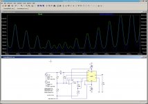
I have found this little circuit that works well, but the effect of the current sensing resistor on sound is an unknown. A Hall sensor sounds like a good idea. Thanks for putting me onto that idea.
The circuit tracks the output power in real time. For a meter some sort of damping effect on the output might be beneficial.
Attachments
Hi,
I think you should look around. I used the Basic micro programming kit for my projects. The Nano 8 Starter Kit cost $29 dollars and the programming software it is free. You can download it from their web side Basic Micro - Robotics & Microcontrollers. There are also Pickaxe, Parallax, BasicX and Zbasic. All the programming software/Editor it is free.
I think you should look around. I used the Basic micro programming kit for my projects. The Nano 8 Starter Kit cost $29 dollars and the programming software it is free. You can download it from their web side Basic Micro - Robotics & Microcontrollers. There are also Pickaxe, Parallax, BasicX and Zbasic. All the programming software/Editor it is free.
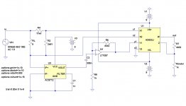
Here is an analog computer that calculates the output power of an amplifier in real time. Actually, just a new version of the circuit I posted earlier I posted earlier. ")
This one uses an ACS712 Hall current sensor. The output is a DC current between 0 and 1mA, intended to drive an analog meter. Full scale deflection corresponds to 300W.
The power supply arrangement is still a bit theoretical. I have now realised that such a power meter would be quite useful as a portable instrument. The opamp and multiplier are therefore powered by 9V batteries, but the Hall sensor is powered by a mythical 8V battery - the maximum supply voltage in the datasheet. A proper supply still needs to be designed with a Zener or voltage regulator.
It would work even better if just one battery is needed. While it would be easy to power the opamp from a single supply, the multiplier would not work as well as before. The operating input and output range of the AD633 is within 3V to 4V of either supply voltage (from the datasheet). For operation on a single supply, the input and output voltages can go no lower than 3-4V above ground or no higher then 3-4V below the supply voltage.On a 9V batter this gives 1-3V of ouput, not ideal but doable.
Attachments
- Status
- This old topic is closed. If you want to reopen this topic, contact a moderator using the "Report Post" button.
- Home
- Amplifiers
- Power Supplies
- How to add a proper power meter to an amp?