An inductor that size will run about 90 to 120 euros plus Vat would it not . plus the size and weight ?You are right that inductors may work until some MHz or so. The rest is the job of a low ESL ceramic capacitor.
But then with toroidal type of inductor and with only 47uH I can see that the windings are not laid on top of each other, unlike a normal air core loudspeaker coil. So in that case perhaps the parasitic capacitance is not that high?
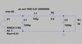
The trouble I have now is that I can't find inductors for my power amp use. Most inductors are rated below 5-10A. Looking at the current draw through the inductor for a 5A power amp, the current runs as high as 13A in a 10000uF-47uH-0.22R-20000uF filter. So a 5-10A inductor will be saturated and become useless, or even produce non-linear distortions. A CLRC filter like that is supposed to produce 80dB reduction at 1MHz, short from 100dB I want.
Any solutions?
5-10A inductors cost under $10. Inductors above 10A are hard to find. The spec may claim 10A but that may sometimes refer to the maximum current. Those 10A inductors from mouser or digikey would have some 20%-50% reduction in inductance when it is run at 10A current.
I remember I saw the big chokes in a big Ayre amplifier and that amplifier ran very quiet in terms of noise.
Who make 20A 47uH chokes?
I remember I saw the big chokes in a big Ayre amplifier and that amplifier ran very quiet in terms of noise.
Who make 20A 47uH chokes?
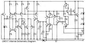
LM317T's circuit is very complex. I wonder why it doesn't have the performance of discrete ones, e.g. Salas.
I can't even begin to figure it out. There doesn't seem to be differential error amplifier in it, for example. But, it is amazing what you get for 47 cents, isn't it?
What about a discrete version of the LM317/LM337 using better parts? Anyone up for a challenge?
Samuel Groner's discrete design is one place to start: http://www.sg-acoustics.ch/analogue.../pdf/discrete_series_voltage_regulator_r1.pdf
It's low dropout (<1 volt input to output), the reference voltage generator is biased from the regulated output ("bootstrapped"), it's protected against short circuits and overcurrent (Q110), and its error amplifier is cascoded for very high gain, giving low output impedance and precise regulation.
Plus he (deliberately?) included a couple of cost-vs-performance tradeoffs in the design, so that others could enjoy tweaking later. I suspect DIYaudio readers may well have their own ideas about what to do with R104 and R107, and whether to convert PNP emitter follower Q107 to a P channel MOSFET source follower.
LM317 as tracking pre-regulator for the LT1963A
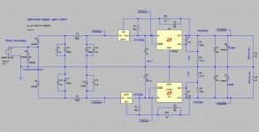
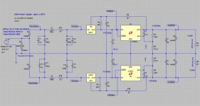
Another thought, below.") Since a pre-regulator of some sort would have to be included anyway before the LT1963A to drop the input below the chip's maximum 20Vdc for what I'm building, a LM317 could simply be used in that spot as a tracking pre-regulator for the LT1963A. Same on the negative rail, the LM337 is a pre-regulator for the LT3015.
Since a pre-regulator of some sort would have to be included anyway before the LT1963A to drop the input below the chip's maximum 20Vdc for what I'm building, a LM317 could simply be used in that spot as a tracking pre-regulator for the LT1963A. Same on the negative rail, the LM337 is a pre-regulator for the LT3015.
In both cases the LM parts maintain the fixed 1.5Vdc across the LT LDOs. Similar to what Jung does with the Super Regulator, except swapping out the transistor regulator for the LT regulator. The LM regulators eat the majority of the ripple same as the diode fed cap multiplier a few posts back, plus maintain a fixed voltage across the LT parts.
The downside is the minimum 3V or so needed across the LM regulators vs. 1Vdc or so for the diode/LED-fed cap multiplier. However since that is the whole point, to consume a few volts to drop the input down below 20 for the LT1963A, I'll call that a feature rather than a bug. The benefit should be allowing the low-noise LT regulators to clean up after the LM regulators
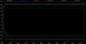
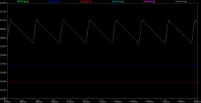
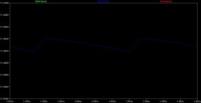
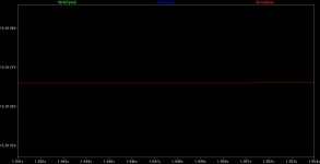
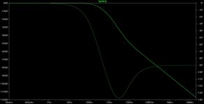
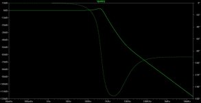
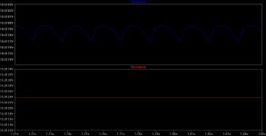
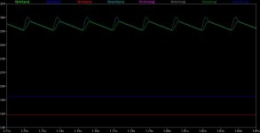
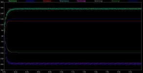
In the sim plots green is the input to the LM317, blue is the output of the LM317 into the LT1963A, and red is the output of the 1963A. 340 mA or so load on each rail. The 3rd plot is the ripple out of the LM317 going into the LT1963A, about 2mV. Whatever ripple is out of the LT1963A in the last plot is below the limits of LT Spice. Any numbers that tiny in a sim are useless anyway, of course. Time to build one, hook it up to a scope and see what the real world ripple is.
Another thought, below.
Since a pre-regulator of some sort would have to be included anyway before the LT1963A to drop the input below the chip's maximum 20Vdc for what I'm building, a LM317 could simply be used in that spot as a tracking pre-regulator for the LT1963A. Same on the negative rail, the LM337 is a pre-regulator for the LT3015.In both cases the LM parts maintain the fixed 1.5Vdc across the LT LDOs. Similar to what Jung does with the Super Regulator, except swapping out the transistor regulator for the LT regulator. The LM regulators eat the majority of the ripple same as the diode fed cap multiplier a few posts back, plus maintain a fixed voltage across the LT parts.
The downside is the minimum 3V or so needed across the LM regulators vs. 1Vdc or so for the diode/LED-fed cap multiplier. However since that is the whole point, to consume a few volts to drop the input down below 20 for the LT1963A, I'll call that a feature rather than a bug. The benefit should be allowing the low-noise LT regulators to clean up after the LM regulators
In the sim plots green is the input to the LM317, blue is the output of the LM317 into the LT1963A, and red is the output of the 1963A. 340 mA or so load on each rail. The 3rd plot is the ripple out of the LM317 going into the LT1963A, about 2mV. Whatever ripple is out of the LT1963A in the last plot is below the limits of LT Spice. Any numbers that tiny in a sim are useless anyway, of course. Time to build one, hook it up to a scope and see what the real world ripple is.
Attachments
-
 LM317 track prereg LT1963A circut 16Vdc.jpg116 KB · Views: 787
 -
 LM317 track prereg LT1963A plot 16Vdc.jpg60.8 KB · Views: 744
 -
 LM317 track prereg LT1963A plot zoom 16Vdc.jpg42.6 KB · Views: 689
 -
 LM317 track prereg LT1963A ripple out of LM317.jpg29.8 KB · Views: 671
 -
 LM317 track prereg LT1963A ripple out of LT1963A.jpg28.3 KB · Views: 203
Last edited:
Looks good! Are you actually going to build it?
I think so! I've just revised the layout to add the 317/337 and a couple of other tweaks. I'll probably send the board out to fab in a week or so whenever I figure out what to add in the remaining board space.
I'm kind of liking the 317/337 pre-regulator thing, the more I think about it today. It guarantees that the input of the LT1963A will never exceed around 17.5Vdc + 0.3Vdc. I was concerned that the diode fed cap multiplier might exceed that with power line fluctuations. Also a bit worse than it seems since from the data sheet fine print notes that 20Vdc maximum input is measured from the output. So if the other rail drops out and the schottky clamps it at -0.2Vdc, that would be 19.8Vdc maximum in. With silicon clamp diodes on the rails it would drop to 19.3Vdc or so. Plus I like to add at least a volt of margin there for part tolerances.
The arrangement uses each part for what it does best. The floating 317/337's float while the ground-referenced LT parts pin down the endpoint voltage. I forgot to mention that the indicator LED resistors on each rail are reduced from 4.7K to 2.7K to pull 5mA through the LEDs. The LM parts need around 5mA minimum load with the 340mA flow but the LT parts only consume about 1mA quiescent. So the LEDs are *required* as load for the LM parts, to take care of the case of the output unhooked to anything.
I've also added 0.5R more in series with the 100uH coils to lower the Q of the CLC filter to nuke some peaking in the sims below. With just the coils and their inherent 0.2R the response peaks slightly. I prefer things on the over-damped side.
Should be interesting to see if the real circuit in any way matches up with the sim results!
Attachments
Last edited:
What is good about the bootstrap connection? How is it better to connect R3 to the LT1963's output, rather than connecting R3 to ground (with suitable R value choice)?
By definition, ground has the least noise of any signal on the board. Connecting R3 to ground injects less noise into the LM317, than connecting R3 to the LT1963's output.
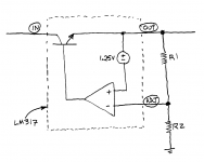
Suppose that an unwanted signal ("noise") does somehow appear on the LT1963's output. R3 and C18 faithfully transmit this signal to the LM317, which faithfully reproduces the signal* on its output -- the input to the LT1963. Oh great, now the LT1963 has more noise on its input, to attenuate. Why is this a good thing?
*inverted -- since the ADJ pin is the inverting input of the LM317's error amplifier, see drawing below
By definition, ground has the least noise of any signal on the board. Connecting R3 to ground injects less noise into the LM317, than connecting R3 to the LT1963's output.
Suppose that an unwanted signal ("noise") does somehow appear on the LT1963's output. R3 and C18 faithfully transmit this signal to the LM317, which faithfully reproduces the signal* on its output -- the input to the LT1963. Oh great, now the LT1963 has more noise on its input, to attenuate. Why is this a good thing?
*inverted -- since the ADJ pin is the inverting input of the LM317's error amplifier, see drawing below
Attachments
I think the big claim to fame of the tracking pre-regulator is maintaining the constant voltage across the downstream regulator. Figure 5 in the datasheet also has that arrangement: http://www.ti.com/lit/ds/symlink/lm317.pdf (opens PDF)
http://www.ti.com/lit/ds/symlink/lm317.pdfExcellent point on the noise. You are quite right from what I can tell, in the reverse direction noise would be conducted to the pre-regulator adjust pin. Probably not a good thing. This would apply to the Jung super-regulator too, wired up the same way.
It would be really interesting to make some measurements on the actual circuit with noise injected at the output and see what happens with that loop through the pre-regulator.
http://www.ti.com/lit/ds/symlink/lm317.pdfExcellent point on the noise. You are quite right from what I can tell, in the reverse direction noise would be conducted to the pre-regulator adjust pin. Probably not a good thing.
This would apply to the Jung super-regulator too, wired up the same way.It would be really interesting to make some measurements on the actual circuit with noise injected at the output and see what happens with that loop through the pre-regulator.
Last edited:
Hmmm... some additional thought... maybe what needs to happen is C18 connected back to ground the standard way rather than to the output of the LT1963A. The whole point of that adj pin bypass is to keep ripple off the LM317 adj pin. Running it to the LT output would just conduct noise backwards, exactly like you say. Running it back to ground should help bypass the noise. As I recall the Jung regulator, at least in the initial paper, didn't include that cap in the tracking regulator portion. Good find!
If the downstream regulator does its job, its output voltage is constant. If the upstream regulator does its job, the upstream output voltage is constant too. So the downstream regulator has constant output, constant input: voila, the voltage across the downstream regulator is constant. Without any tracking / feedback connection.I think the big claim to fame of the tracking pre-regulator is maintaining the constant voltage across the downstream regulator
You want the LT1963's input voltage to be 17.5 volts. You can accomplish this by changing R3 to 3.16K, then connecting both R3 and C18 to ground. What aspect of circuit performance is improved, if you connect R3 to the downstream output instead? What is the benefit? If there isn't a benefit, why do it?
OK, OK, I'm convinced, lol. Seriously though, thanks to both you guys for the input. Much appreciated. Interestingly enough the bootstrap reg method with the 10uF from adj to ground did lower ripple from the first reg in the sim by an entire order of magnitude, from 2mV to 200uV. Both numbers being too small to be believeable in a sim, I know, but the order of magnitude thing probably has some general merit.
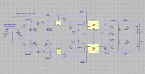
But... with the series reg method, second sim circuit below, the results are the same (good) 10x reduced ripple out of the first reg, down to 200mV ripple. I would agree with you both, after some further thought here, that the series method is probably going to be less of a real-world stability challenge. jcx- I definitely agree that that Spice is going to be of limited use here in detecting stability issues. A good design upfront is the best defense. In the sim and layout I've used transistormarkj's 3.16k's.
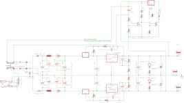
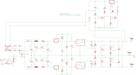
The first spice circuit below is the (now discarded) bootstrap reg method. Second is the series reg. I've put in parameters now for a better-defined transformer, a WAU24-1000 or WAU24-1800 with about 2.4R secondary. This weekend I'll see if I can stuff in the full transformer coupled inductor model for fun.
Also going to see if I can fit in SMD pads on the bottom of the board under the rectifier diodes for optional series resistor+cap snubbers.
Seriously though, thanks to both you guys for the input. Much appreciated. Interestingly enough the bootstrap reg method with the 10uF from adj to ground did lower ripple from the first reg in the sim by an entire order of magnitude, from 2mV to 200uV. Both numbers being too small to be believeable in a sim, I know, but the order of magnitude thing probably has some general merit.But... with the series reg method, second sim circuit below, the results are the same (good) 10x reduced ripple out of the first reg, down to 200mV ripple. I would agree with you both, after some further thought here, that the series method is probably going to be less of a real-world stability challenge. jcx- I definitely agree that that Spice is going to be of limited use here in detecting stability issues. A good design upfront is the best defense.
In the sim and layout I've used transistormarkj's 3.16k's.The first spice circuit below is the (now discarded) bootstrap reg method. Second is the series reg. I've put in parameters now for a better-defined transformer, a WAU24-1000 or WAU24-1800 with about 2.4R secondary. This weekend I'll see if I can stuff in the full transformer coupled inductor model for fun.
Also going to see if I can fit in SMD pads on the bottom of the board under the rectifier diodes for optional series resistor+cap snubbers.
Attachments
-
 ODA PS bootstrap regs spice circuit.jpg124 KB · Views: 461
 -
 ODA PS series regs spice circuit.jpg141.9 KB · Views: 455
 -
 ODA PS series regs plot zoom 2.jpg41.8 KB · Views: 140
 -
 ODA PS series regs plot zoom 1.jpg42.3 KB · Views: 144
 -
 ODA PS series regs plot.jpg60.3 KB · Views: 355
 -
 ODA PS circuit.png35.2 KB · Views: 300
 -
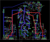
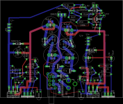 ODA PS layout.png38.8 KB · Views: 303
Last edited:
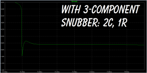
Also going to see if I can fit in SMD pads on the bottom of the board under the rectifier diodes for optional series resistor+cap snubbers.
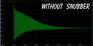
Oscillatory ringing occurs when the rectifier diode cuts off; it's a parallel LC circuit consisting of the transformer's secondary leakage inductance, and its secondary capacitance (in parallel with the rectifier's junction capacitance). The ringing can be damped ("snubbed") by adding a third parallel leg, a resistance, forming a parallel RLC circuit. A wise choice of R gives a well-damped waveform with (0.5 < zeta < 1.2) and no ringing.
This means that the snubber is placed in parallel with the transformer secondary, as shown in Figure 7 of Hagerman's paper http://www.hagtech.com/pdf/snubber.pdf . That figure's snubber is (Rs, Cs, Cx) and it is in parallel with the transformer secondary (Lt, Ct).
Remember, the rectifier is merely the agent provocateur, the initiator, the wooden hammer that whacks the bell. The bell is what rings, and the bell is what needs damping.
As Hagerman shows, this can be simulated. After measuring your transformer's secondary leakage inductance Lt and its secondary interwinding capacitance Ct, and after consulting your rectifier's data sheet to find its zero bias junction capacitance, you can build an LTSPICE model and experiment with snubbing. An example from a lab bench power supply I just built, using a TRIAD VPS36-2200 VPS36-2200 Triad Magnetics | Mouser transformer, is attached.
Compare the waveforms to Hagerman's Figures 9 and 10.
Attachments
transistormarkj - sounds good! Across the secondary they go. I think that will be an easier layout job too.
jackinnj - yeah, I've been pondering that Kelvin connection. That figure is for the "fixed" voltage version of the LT1963A though, where it looks like they rebrand the "adj" as "sense". With the adjustable reg I wonder if the equivalent thing is as figure 3 here http://cds.linear.com/docs/en/datasheet/lt0117.pdf for the LT317, with the output-to-adj resistor close to the reg but adj-to-ground resistor returned to remote ground?
From past experience I better make that a "negative option" connection where sense is normally connected to the output and something has to be cut/switched/removed to remote it. I spent several hours with the first switching supply I ever used, years ago, trying to get the thing to work. Eventually discovered a sense connection needed to be connected, but no markings/instructions/manual.
- Status
- This old topic is closed. If you want to reopen this topic, contact a moderator using the "Report Post" button.
- Home
- Amplifiers
- Power Supplies
- Modern 317/337 alternatives?