Thanks for your valuable subjective evaluation report and I take it seriesly. From your measured data, it is unbelivable that the Burson reg could sound good, as it measured 10 times worse than the humble LM317/337. I built the LM317/337 no less than 6-7 times in the past 10 years and I did not like the sound for the first 5-6 times, but the last build did give quite good sound.
Is the Sjostrom' a derivation from the Jung reg? I have not found any information on that one.
WRT the Burson, I couldn't believe it myself!!! I purchased all the regulators from their distributors so there weren't any ex ante bias likelihood (i.e. reviewer samples that are especially tricked out.)
The Sjostrom boards are available from Per Anders, the design is pretty similar to the Jung.
I did state in the article that I chose a line amp circuit with "only fair" PSRR at the suggestion of one of DIYAUDIO's moderators. The Borbely "All JFET" is a fantastic sounding line amplifier but PSRR is only about 40dB. If one used one of the high end TI opamps like the OPA2604 or 637 instead of the all-discrete JFET design, perhaps the differences wouldn't be as noticeable.
Jackinnj,
I checked that site and only got the graphs. I have not seen the article. Perhaps I will need to registor before I can see the article.
According to Belleson's site, their regulators have at maximum 7mR at 40kHz. Your measurement deviated much from that.
I guess I will need to read your article to see how the graphs were derived. Since it is public information and no longer confidential, could you post the article here if you own the copyright?
Regards,
Bill
Last edited:
The regulators which just stood out above all else were the Jung, Sjostrom, Burson, NCD and Linear Tech LT1963A/LT3015. They were in a class all by themselves.
Interesting that you don't include the Salas in this list as on the graphs it seems to perform consistently among the best of the best.
I think it heavily depends on implementation. Circuit layout, input stage, the type of load, how much current you run, how long the piece of wire connecting to the input and load, use of remote sensing, etc, all can have a big impact on sound. If all are taken care of properly, in terms of sound I would take the regulator with the best measured spec any time any day. I guess among that list, the Salas reg and the Jung reg stand ahead of others.
Interesting that you don't include the Salas in this list as on the graphs it seems to perform consistently among the best of the best.
We had the Salas in the group tested since it seems to be a highly popular design. I used the boards burned by one of the group members. They never made it into the top cohort of the listening tests.
One of the issues one might have with the Salas is that it seems to be a continually evolving work. One of the problems of the web, unlike a journal, is that a definitive design isn't published as a benchmark. If someone comes up with the reference design, I will be happy to retest but I count over 20 versions in the several threads related to the device. In fact, I would like to compare it with the design Jung described in the AX interview.
Guys, what would be the most important criteria for digital circuit? (e.g., clock, receiver, DAC) Low z-out, low noise or high PSRR? BTW, does low z-out also imply fast transient response? Thanks.
I would assume it would be high current capacity and low source impedance.
We had the Salas in the group tested since it seems to be a highly popular design. I used the boards burned by one of the group members. They never made it into the top cohort of the listening tests.
One of the issues one might have with the Salas is that it seems to be a continually evolving work. One of the problems of the web, unlike a journal, is that a definitive design isn't published as a benchmark. If someone comes up with the reference design, I will be happy to retest but I count over 20 versions in the several threads related to the device. In fact, I would like to compare it with the design Jung described in the AX interview.
hmm.. well it makes me wonder what metric would correlate with the comparative sonics.
Indeed why not place a similar attenuator into the other, negative, leg of the supply as well?
Good thoughts!
In my original layout I did have one on the negative rail, just for symmetry. I used a 1N4148 diode there instead of a LED since I didn't need any voltage drop. I've been thinking about adding that circuit back. From past experience it seems like every time I design something asymmetric like that thinking it won't matter, it does.
") Plus opens the door for a drop on the negative rail if a higher voltage input was used and really did need to knock it down to -30Vdc.
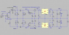
Plus opens the door for a drop on the negative rail if a higher voltage input was used and really did need to knock it down to -30Vdc.I also simulated adding in a cap multiplier, R5 and C5. I wound up with 22R and 100uF. I'm thinking of adding that in, too. That one is sort of a "why not?" The circuit is already 50% of the way to a cap multiplier, might as well add the two parts. A 100uF solid polymer electrolytic is small and cheap these days, with just 25mR ESR, Mouser 647-RL81V101MDN1KX. The error amps in regulators seem to be more than fast enough to cope with the sharp corners on the incoming 60Hz or 120Hz sawtooth, the diode cut-off. But something in my head keeps thinking about the Fourier decomposition of those corners and isn't liking it. I would prefer to have them rounded going into the regulator chip. Plus, as you say, even though the regulator ripple out of the regulator is already too small to believe sim results, small/atten is likely to be better than big/atten.
R3 and Q3 are new. Is that to spread the power dissipation over two transistors? I see the top one starts turning on at 21mA.
Last edited:
R3 and Q3 are new. Is that to spread the power dissipation over two transistors? I see the top one starts turning on at 21mA.
They reduce the base current of Q2. Without R3+Q3, Q2's base current is (350mA / Beta). With R3+Q3, Q2's base current is (21mA / Beta). Less base current allows you to increase R5 without decreasing the final output voltage. Larger R5 means a longer RC timeconstant, better filtering, and less ripple.
Edit- oops, forgot to mention that Q2+Q3 are a complementary feedback pair and as such, get all of the advantages of http://www.fidelityforce.com/keantoken/content/Kmultiplier.html including lower output impedance.
Last edited:
hmm.. well it makes me wonder what metric would correlate with the comparative sonics.
There are a ton of articles in the Journal of the Audio Engineering Society which try to deal with this exact issue. It isn't easy, but I would suggest that PSRR at the very low frequency extremes and output impedance are far more important than noise.
I just ran this PSRR test of the Belleson SPL17 and a Fairchild 7815 -- you can see that the rejection is very good. It's not quite what you see from the company's data here Superpower Super Regulator by Belleson because the input voltage is less. The chart on their website should reference a ratio, rather than absolute voltage.
An externally hosted image should be here but it was not working when we last tested it.
The instrument i am using injects a smaller perturbation voltage into the DUT
Guys, what would be the most important criteria for digital circuit? (e.g., clock, receiver, DAC) Low z-out, low noise or high PSRR? BTW, does low z-out also imply fast transient response? Thanks.
It's only the low noise that really matters with digital. No regulator can offer meaningfully low Zout at the tens or hundreds of MHz where clocks these days run - at such frequencies one has to rely on cap decoupling.
It's only the low noise that really matters with digital. No regulator can offer meaningfully low Zout at the tens or hundreds of MHz where clocks these days run - at such frequencies one has to rely on cap decoupling.
A clock running at some tens of MHz still has to deal with longer duration pulses crud on Vcc which can disorient a comparator etc.
I think that what could be problematic with one of these regulators is low phase margin in the MHz. You can determine phase margin without disturbing the feedback loop --
I think we're getting beyond the intent of the thread starter, here.
I also simulated adding in a cap multiplier, R5 and C5. I wound up with 22R and 100uF. I'm thinking of adding that in, too. That one is sort of a "why not?" The circuit is already 50% of the way to a cap multiplier, might as well add the two parts. A 100uF solid polymer electrolytic is small and cheap these days, with just 25mR ESR, Mouser 647-RL81V101MDN1KX. The error amps in regulators seem to be more than fast enough to cope with the sharp corners on the incoming 60Hz or 120Hz sawtooth, the diode cut-off. But something in my head keeps thinking about the Fourier decomposition of those corners and isn't liking it. I would prefer to have them rounded going into the regulator chip.
Have you tried an LC or a CRC filter after the rectifier? Either one smooths out the sawtooth considerably, at a small loss of pre-regulator voltage.
They reduce the base current of Q2. Without R3+Q3, Q2's base current is (350mA / Beta). With R3+Q3, Q2's base current is (21mA / Beta).
That is an excellent idea! I see, essentially a Sziklai pair alternative to a Darlington, set up to kick in at 21mA.
Have you tried an LC or a CRC filter after the rectifier? Either one smooths out the sawtooth considerably, at a small loss of pre-regulator voltage.
I completely agree. Last night I wound up stuffing in two 100uH chokes between the two 1200uF main filters. The chain of thought was originally thinking of making CRC filters with 0.2R resistors between the caps. But then got to thinking that the inherent resistance in a small choke would be about that. Sure enough, #580-12LRS104C at Mouser has 100uH and 0.2R, along with 1.4A burst rating (cap charging current). So using the inductor gives C-(L+R)-C.
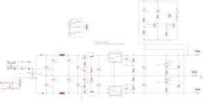
Below is the result. BTW, this isn't commercial. This is part of a DIY headamp in another thread and I'll eventually be posting the Gerbers here in the wiki section on DIYA if anyone wants to DIY it once I get the boards stuffed and verified. This is a 80x100mm board that would fit in a B2-080 or B3-080 aluminum enclosure (Allied Electronics or Newark), or in this project half of a B3-160 with the amp 80x100 in the other half.
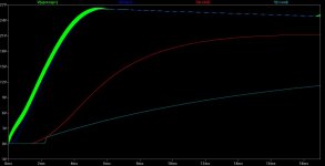
The green in the LT Spice plot is before the inductor and 2nd cap (positive rail) while the blue is post inductor. I've injected 1Vpeak of 2mHz noise after the diodes (diode bleed through at high frequencies). That fuzz on the green trace after the t0+ startup is the HF noise. The CLC filter, blue trace output, does a good job of cleaning it up. This is in addition to tombstoning the rectifiers and putting ferrites over the leg for high(er) RF filtering.
Attachments
Last edited:
Have you tried an LC or a CRC filter after the rectifier? Either one smooths out the sawtooth considerably, at a small loss of pre-regulator voltage.
I think that is a good idea, an idea I am currently re-exploring.
Most regulators have good PSSR at low frequencies and poor PSSR at higher frequencies. A simple, cheap CLRC filter can easily achieve PSSR of over 100dB above 10kHz, and remain effective to perhaps the GHz region. So for PSSR, i.e. for line regulation, at higher frequencies, the CLRC filter is at work. At lower frequencies, the regulator is at work. It is the best of both worlds.
Is there any problem? Maybe, on the impedance side, i.e. load regulation.
The impedance seen at the input of the regulator will increase considerably by the total R of the filter circuit. So now it all depends on if the regulator can deal with this impedance increase and can still delivery a low impedance output.
The regulator in conjuction with capacitors can possibly deliver a low impedance output at higher frequencies, negating the effect of the input impedance increase. However, this is not the case at lower frequencies unless we use hundreds of thousands of uF capacitance, which is not practical.
This means the overall end result for the regulator is much improved PSSR at high frequencies but increased output impedance at lower frequencies (usually below a few hundreds Hz).
But perhaps this is not a problem, because most amplifiers have high PSSR at lower frequencies so the high output impedance at low frequencies of the regulator does not impose a problem on the amplifiers.
Are I right? Please point out my errors if you see any.
inductors aren't that good - parasitic winding C shorts HF right through them, so they only have limited bands of effective hi Z/blocking ability
to inductively attenuate up to GHz you need multiple differing core materials and winding construction
in addition to lumped parasitic C - at high enough frequency EM can take to the air, leaving intervening "filtering" circuits behind
to inductively attenuate up to GHz you need multiple differing core materials and winding construction
in addition to lumped parasitic C - at high enough frequency EM can take to the air, leaving intervening "filtering" circuits behind
You are right that inductors may work until some MHz or so. The rest is the job of a low ESL ceramic capacitor.
But then with toroidal type of inductor and with only 47uH I can see that the windings are not laid on top of each other, unlike a normal air core loudspeaker coil. So in that case perhaps the parasitic capacitance is not that high?
The trouble I have now is that I can't find inductors for my power amp use. Most inductors are rated below 5-10A. Looking at the current draw through the inductor for a 5A power amp, the current runs as high as 13A in a 10000uF-47uH-0.22R-20000uF filter. So a 5-10A inductor will be saturated and become useless, or even produce non-linear distortions. A CLRC filter like that is supposed to produce 80dB reduction at 1MHz, short from 100dB I want.
Any solutions?
Last edited:
- Status
- This old topic is closed. If you want to reopen this topic, contact a moderator using the "Report Post" button.
- Home
- Amplifiers
- Power Supplies
- Modern 317/337 alternatives?