Hi All,
I get a really large voltage drop when I connect the amps to the SPS01 power supply. NEG-Ground = -17VDC and POS-GROUND= 22VDC
Unloaded the voltages are 33VCD.
I have a toroid from Amplimo whitch provides 2 x 25VAC at 10 Amps.
I mounted rectifiers: 8x MOSPEC U30D20 rectifiers. The datasheet of these rectifiers state that the operating voltage should be between 50 and 200V. I supply 25VAC.
So I see 2 strange things:
1: It takes upto 3 minutes for the SPS01 to go from 0 to 33VDC.
2: When load is applied, the voltages drop dramaticly to 17 and 22 VDC.
Question: What could be the problem?
Kind regards,
Sjoerd Smits
Have you got for smoothing capacitors? If so Are you using a CRC or just C Also how large are the capacitors? if you are using CRC, what is the value of the resistor and how much current is the amp drawing?
edit: the 50 - 200V rating is for the different models. the U30D05 model has a maximum of 50V, the U30D20 has a maximum of 200V.
Tony.
edit: the 50 - 200V rating is for the different models. the U30D05 model has a maximum of 50V, the U30D20 has a maximum of 200V.
Tony.
Last edited:
Capacitance: 22000
Lower Cap Tolerance: 20
Upper Cap Tolerance: 20
Working Voltage: 63
Surge Test Voltage: 72.5
Terminals 2 PIN SNAP-IN
Other Dimensions
Rated ripple current 10.5 A rms at 100 Hz and 85
Diameter (mm) 40 -0/+1
Length (mm) 80 +/-2
Temperature range -40 °C to 85
ALC10S1082EL
There are 8 of these on the PSU...
I Measured the amp idle. Nothing connected to it... Do you think the slow power up is strange?
Very.
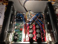
Measure the AC voltage to the rectifiers during start up and maybe post some pics of the set up.
88,000uF per rail is quite a bit and would take a while to stabalise but 3 minutes to reach 33V seems excessive.
I'd check that you don't have a high resistance joint on the secondaries, where they are connecting to the PS board. It seems like you have some significant resistance somewhere in the circuit. If you know what the resistance of your secondaries are, then try measuring it on the board at the rectifier AC pins (make sure it has properly discharged first though).
edit: Also as AndrewT always asks, are you using a light bulb tester?
Tony.
Last edited:
On here ")
To add a photo, files or non standard files.
First click "go advanced" in the box below the "quick reply" message box. Doesn't matter if you decide half way through a message to do that, it carries it foward.
Then click "Manage attachements". Maximise the new Window so that you can see all the text.
Click browse in the first box at the top and find your picture. Repeat for any more pictures.
Click upload... a message appears "uploading"
When complete the files will show as being attached. Now click the small text that says "close this window"
The pictures should now be attached and when you submit your post they will appear.
Make sure your pics aren't too big, a couple of 100k is plenty, and many members object when they are massive and it alters the margins
It tells you in the attachments window what max sizes are allowed.
If you want to attach a file that has a non standard format for example excel, circuit simulation etc then try putting the files in a zipped folder and attaching that."
There is definitely something screwy there!! Have you measured the resistance of the transformer secondaries when disconnected from the board?
I wonder if the transformer has a built in fuse. if it does, with the amount of capacitance you have on the PS you may have blown it (it may just go very high resistance, could even possibly be a polyswitch). You may need a soft start circuit.
Tony.
I wonder if the transformer has a built in fuse. if it does, with the amount of capacitance you have on the PS you may have blown it (it may just go very high resistance, could even possibly be a polyswitch). You may need a soft start circuit.
Tony.
Think about it... be logical
Switch on and you have 25 volts AC applied to the rectifiers. Yes ? I can't explain your meg ohm reading other than to say that either the meter is faulty or that there is some DC voltage confusing the reading or that you are trying to measure through some insulation or varnish etc. 25 volts applied to the diodes is proof enough that the tranny output is OK.
The 33 volts climbs slowly. If there were a short or a real low resistance path somewhere then a huge current should be flowing and something should be getting hot. Is it ? Are any diodes getting hot during this time ?
Could the diodes be fake ?
Hi Wintermute and Mooly,
The resistance on the secondary's is "zero" Ohm. I get a perfect 25VAC out of both secondarys.
I do use a softstart(see picture from before) and even a DC trap to cancell out toroid "Hum". To be sure that the softstart or DC trap weren't defective, I have also measured without those circuits.....
Fake diode's? I got them from Per-Anders himself... so I don't think so.... Nothing gets "hot" only a bit warm but nothing serious....
- Status
- This old topic is closed. If you want to reopen this topic, contact a moderator using the "Report Post" button.
- Home
- Amplifiers
- Power Supplies
- Huge voltage drop on PSU