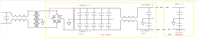
Is that a common-mode or differential-mode choke? Either would be inappropriate in that position. CM-mode would fail because you have grounds either side of it, thus removing any small benefit from it. DM-mode would fail because you can't assume that the two ripple currents/voltages will be the same.
Two separate chokes would work, but for some strange reason CM-mode chokes have suddenly become popular and so get sprinkled around circuits like magic dust.
Two separate chokes would work, but for some strange reason CM-mode chokes have suddenly become popular and so get sprinkled around circuits like magic dust.
Is that a common-mode or differential-mode choke? Either would be inappropriate in that position. CM-mode would fail because you have grounds either side of it, thus removing any small benefit from it. DM-mode would fail because you can't assume that the two ripple currents/voltages will be the same.
Two separate chokes would work, but for some strange reason CM-mode chokes have suddenly become popular and so get sprinkled around circuits like magic dust.
Thanks for making it easy for me, by asking a question and answering it in the same thread. Now that's team work
")
Some good advice and good observations mixed in with complete coddswallop.
1. mandatory?
3. other rectifiers?
4. slow down the main reservoirs transient response?
. We do not want this part of the PSU responding to transients?
6. Use decoupling caps to ensure that the transient slows down?
8. Use a filter between main reservoir and decoupling?
Does anyone agree with "every" suggestion of OnAudio?
Did the scope and your ears tell you any different
?but, such a device does not by itself solve the peak current demand problem.
The emf driving the current and the capacitor demanding the current in response to the emf will try to charge the capacitor in one quarter cycle. The SS relay timed to close at zero crossing will still suffer an enormous current pulse.
One must consider the components in the charging circuit and decide what the one shot peak current can be to allow all components to have a long lifetime. That peak current may be limited by some slow charging circuit.
If one decides that a slow charging circuit is required, it can be as simple as an added resistance in the charging circuit.
My reply was only about this
the transformer will provide as much current as the capacitors demand. which is, how much? is it limited? i think not. So it will peak. Perhaps then a circuit should delay turning on the psu until the AC crosses zero so at least that way it won't be BAM max current to the caps
I didn't answer my own question. I just pointed out why either answer would be wrong. Of course it could be that the apparent coupled chokes in your PSU circuit are not coupled at all but merely drawn badly. Separate chokes in the two lines would work, but one of them would be unnecessary.OnAudio said:Thanks for making it easy for me, by asking a question and answering it in the same thread. Now that's team work
I didn't answer my own question. I just pointed out why either answer would be wrong. Of course it could be that the apparent coupled chokes in your PSU circuit are not coupled at all but merely drawn badly. Separate chokes in the two lines would work, but one of them would be unnecessary.
Despite the abuse of the choke symbol, they are all necessary. The conceptual model is correct in relation to the theory behind it as well as supporting field studies. The first set of chokes make up the line filter. In most PSU the chokes between the caps are replaced by a resistor or a pi filter, the purpose is the same.
My reply was only about this
the transformer will provide as much current as the capacitors demand. which is, how much? is it limited? i think not. So it will peak. Perhaps then a circuit should delay turning on the psu until the AC crosses zero so at least that way it won't be BAM max current to the caps
Of course it's limited. Otherwise the peak would be to infinity, and infinitesimally-short in duration. (Well, if it were truly unlimited it would also last for all time. I was assuming that the capacitor's capacitance was not infinite.)
There are no ideal components or conductors. Transformer windings have R, L, and C. Capacitors have R, L, and C. Wires and traces have R, L, and C. Everything does. Which ones are significant is an important question, of course. In this case, the R and L of the transformer windings, and the R of the capacitor, and the R and L of the wiring to the location's electric service's pole transformer (et al), are all significant.
Also, just FYI, switching on at the AC line's zero crossing will not necessarily give the best behavior. It can depend on what the AC's phase angle was when the transformer was last switched off, i.e. in what magnetizaion state the core was left. But I think that if you controlled both switch off and switch on for the AC's phase angle (in relation to zero crossing), then you could achieve some sort of best-case (or at least more-predictable) peak inrush behavior. I forget the details, at the moment. But that still only means you could probably avoid the occasional worst-case inrush. Of course, the normal inrush might still be too much.
But there are relatively easy and cheap ways to slow it down and limit the peak values to almost any desired level.
But, as AndrewT was saying, first you would need to determine if it was even necessary. If the time-duration is short-enough, many components can withstand peak values that are tens, hundreds, or even thousands of times their rated maximums. Some manufacturers' datasheets do contain that information. I had to find and use such data for a resistor in a power supply peak-inrush-limiting circuit that I designed, once. I used a big MOSFET to detour the inrush current through a low-value resistor on its way to the capacitors, until the rail voltage got high-enough. A resistor that was rated for the current level needed would have been far too large (and costly). I found that according to the manufacturer's datasheet, for the 2 ms or so that the inrush-limiting circuit would operate, the resistors I was looking at could safely dissipate over 500X their rated power, which they did, and never even got the least bit warm.
If you want to worry about peaking, another probably more-important consideration would be the steady-state peaking, after the initial inrush is over. It's just the way this type of power supply circuit operates. The capacitors usually charge with short spikes of current. That's why a lot of people worry about "Power Factor" and use more-advanced circuit topologies for their power supplies.
Cheers,
Tom
Last edited:
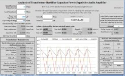
Who wants to be a beta-tester, for my spreadsheet? It's attached. I did it with Excel 2007 but saved it as a plain .xls file, so it might work with older versions of Excel.
It actually emulates the second-order differential equation for a transformer-rectifier-capacitor circuit, including leakage inductance and resistance of the transformer windings, and uses a non-linear model of diode resistance vs current. It uses a fourth-order Runge-Kutta iteration algorithm.
It automatically switches back and forth between the full second-order equation and a first-order one, depending on whether or not a charging pulse is occurring. So it can accurately plot the output waveforms versus time.
It also includes the scalable transformer modeling from measurements. So you can change the transformer size and ratings at will, and can use any transformer you can measure.
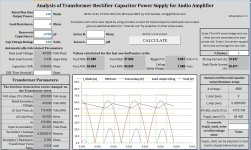
You get to enter some parameters and it calculates everything else, and plots some of it. It also has provisions for overriding the calculated capacitor ESR value. And you can enter an additional series resistance and an additional series inductance, if you want. I've attached a jpeg image of the main screen.
It works really well but there are a few things I'm still not certain are correct, such as the diode modeling for different circuit topologies, and the way the transformer parameters are used. But it closely matches my LT-Spice simulations for "normal" cases.
It does NOT yet let you specify a ripple amplitude and pick a capacitance for you. I'm just trying to get the basic analysis correct, with this one. But it's still a very useful tool.
Also, it's very slow. It evaluates the differential equation 4000 times, to produce a few tens of milliseconds of output. So it takes about 40 seconds to calculate, on my little computer. But it also provides things like min and max output voltage, rms and avg output voltage, ripple amplitude, peak diode and capacitor currents, et al.
I think it should be quite useful.
Note that you have to enable macros, in Excel, for the Calculate button to work.
Let me know what you find wrong with its current capabilities.
Cheers,
Tom
It actually emulates the second-order differential equation for a transformer-rectifier-capacitor circuit, including leakage inductance and resistance of the transformer windings, and uses a non-linear model of diode resistance vs current. It uses a fourth-order Runge-Kutta iteration algorithm.
It automatically switches back and forth between the full second-order equation and a first-order one, depending on whether or not a charging pulse is occurring. So it can accurately plot the output waveforms versus time.
It also includes the scalable transformer modeling from measurements. So you can change the transformer size and ratings at will, and can use any transformer you can measure.
You get to enter some parameters and it calculates everything else, and plots some of it. It also has provisions for overriding the calculated capacitor ESR value. And you can enter an additional series resistance and an additional series inductance, if you want. I've attached a jpeg image of the main screen.
It works really well but there are a few things I'm still not certain are correct, such as the diode modeling for different circuit topologies, and the way the transformer parameters are used. But it closely matches my LT-Spice simulations for "normal" cases.
It does NOT yet let you specify a ripple amplitude and pick a capacitance for you. I'm just trying to get the basic analysis correct, with this one. But it's still a very useful tool.
Also, it's very slow. It evaluates the differential equation 4000 times, to produce a few tens of milliseconds of output. So it takes about 40 seconds to calculate, on my little computer. But it also provides things like min and max output voltage, rms and avg output voltage, ripple amplitude, peak diode and capacitor currents, et al.
I think it should be quite useful.
Note that you have to enable macros, in Excel, for the Calculate button to work.
Let me know what you find wrong with its current capabilities.
Cheers,
Tom
Attachments
Last edited:
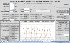
Here's one with a plot of startup from zero volts with a 10000uF cap drawing a 135 Amp current spike (althought spice gives closer to 150 Amps for this case).
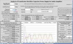
And the second one shows what happened at startup after I inserted a randomly-chosen 0.47 Ohm resistor and 1 mH inductor in series in the power rail, before the cap.
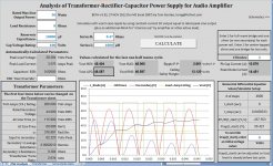
The last two show what can happen when ESR is increased from 0.2 to 2.0 Ohms.
And the second one shows what happened at startup after I inserted a randomly-chosen 0.47 Ohm resistor and 1 mH inductor in series in the power rail, before the cap.
The last two show what can happen when ESR is increased from 0.2 to 2.0 Ohms.
Attachments
Last edited:
Hi, Tom, looking a bit lonely here - see what happens when you don't hang around for awhile!
I don't use Excel on my m/c, rather Open Office, an older version, and it's having difficulties opening your spreadsheet - I had to kill the program which was just spinning its wheels doing nothing. Not sure what the problem is, see what other people's experiences are ...
Frank
I don't use Excel on my m/c, rather Open Office, an older version, and it's having difficulties opening your spreadsheet - I had to kill the program which was just spinning its wheels doing nothing. Not sure what the problem is, see what other people's experiences are ...
Frank
Tom it works without hangups I use a 12 year old version of excel and it seems fine. Your spreadsheet looks very interesting and I would like to play with it a little to just get familiar with all the variables and what I see. Thank you very much for all your input so far.
Hi, Tom, looking a bit lonely here - see what happens when you don't hang around for awhile!
I don't use Excel on my m/c, rather Open Office, an older version, and it's having difficulties opening your spreadsheet - I had to kill the program which was just spinning its wheels doing nothing. Not sure what the problem is, see what other people's experiences are ...
Frank
Hi Frank!
Looks like you're past due for a software upgrade, my friend! I would have thought that Open Office would have handled the xls file. But it uses a macro written in Visual Basic so maybe that's a problem? I had Open Office but it's on a PC that will no longer boot.
I finally broke down and bought MS Office Home and Student 2007, a couple of years ago. It was a little over $100, I think, at Staples, and is licensed for up to three home PCs. Staples now has 2010 and 2011 versions, for $90 to $149. The Solver is pretty cool, and apparently got a lot better with the 2007 version. (I didn't use it for this spreadsheet. Just plain old "numerical methods".)
Sorry I've been gone for so long. I was sick for about two weeks straight, with two different ailments. And a lot of "family stuff" happened. And I was maniacally working on hand-written mathematical analyses of this thing, quite a bit, along with the other spreadsheet I have that is supposed to find the absolute-minimum capacitance (among other things). My math skills and memories were/are so rusty that it took about a hundred times longer than it should have, as I had to try to re-learn an awful lot. I am glad that I did that, though. I have re-learned quite a lot of calculus, and differential equations, and signal and system theory (not to mention trig identities), and it feels pretty good.
Now I think I need Maple, and Matlab, and a few others like that. We have many Matlab licenses at work, and lots of Labview stuff, but no Maple.
Anyway, I got a bit disgusted with the other spreadsheet I had been working on, which was basically trying to find the solution without having to actually find the solution. So I decided to write this one, first, so I would at least have the "real" solution, somewhere other than in LT-Spice. And it only took about a day to get this one to the point where the numerical solver was working and plotting the results. Then I spent another few days prettying it up and adding the transformer modeling.
Now that I know a little more about how the circuit equations should work, I will probably try to go back and take a fresh look at them and see if I can finally succeed at deriving closed-form expressions for the few things needed to be able to make a NON-iterative spreadsheet that can calculate just the things that I originally wanted, which, I think, are basically just the max and min output voltages vs C and vice versa, given the other parameters.
But first there are still a few things in this one that I don't quite have nailed down. (Terry Given could probably do them in his sleep.): 1) For the differential equation, I need to transform the transformer model so that there is nothing on the primary side, such that there is just an ideal transformer and then the equivalent series Rs and equivalent series Ls on the secondary side, if that's possible (or whatever needs to be on the secondary side to make the overall transformer be equivalent, with nothing on the primary side). It should be straightforward. I'm just not quite sure about it, yet. Also, 2) I need to verify that the diodes are being correctly accounted-for. Once (1) is verified, then (2) should be much more straightforward. Right now, I've basically got some "fudge factors" on the total diode resistance, to make the results match LT-Spice's results, and it's bothering me.
If you can get into the spreadsheet and look at the VBA code, you'll be able to see what I mean.
Overall, this has been a very interesting circuit/math problem to try to solve. It basically always comes down to a transcendental equation that has no closed-form solution. i.e. After the diodes turn off, it's just a first-order differential equation for the capacitor voltage decay due to the load current, with a solution like e to the minus something t (or, even better, a straight line, in this case, since the load is constant-current). BUT, to then find out when the diodes turn back on (i.e. where the decaying cap voltage intersects the rectified sine), you have to say that something proportional to e to the minus something t equals some sinusoid. And that's a transcendental equation with no closed-form solution (except in certain special cases where you can use the LambertW function, which is w times e to the w).
But there are a couple of tricks that can be used. One is to use Taylor Series representations of the exp and/or sine functions, so that the equation is basically just a polynomial. It's also possible to approximate a sine with a parabola, pretty well, over a limited range of angles (like 0 to Pi/2, or 0 to Pi). But, as is often the case, the devil is in the details. At any rate, if expressions can be found for the turn-on and turn-off times or phase angles, then expressions for the min and max voltage shouldn't be far behind. Conceptually, it all seems easy. My rusty math skills are the main problem.
P.S. I can see why a lot of people who tried this problem in the past left out the transformer and its inductance. BUT, without the inductance, you could never see the output voltage go above the input voltage, like it does in the third image in post 1611! So then the discharge downslope wuld start at the wrong level, i.e. too low, and you would obviously get an incorrect minimum voltage, too (also too low). That's another reason that simpler models only work when the ripple voltage is small, or the capacitance is "large enough". (Maybe I should also have the spreadsheet do the "standard approximate calculation" method and plot that for comparison.)
Cheers,
Tom
Tom,
there's something wrong with the spreadsheet.
The formula for max power and related current shows an error of 40mAac.
100W into 8r0 is 5Aac, not 5.04Aac.
The turns ratio shows as 2.634. (115.9/44)
This is wrong, the rated output voltage does not give the turns ratio.
You need the actual input voltage and the actual output voltage, without a load, to give turns ratio.
Last edited:
Tom it works without hangups I use a 12 year old version of excel and it seems fine. Your spreadsheet looks very interesting and I would like to play with it a little to just get familiar with all the variables and what I see. Thank you very much for all your input so far.
Hi, Nico!
It should be a pretty good tool. It's just a "what if" analyzer. You can put in your max rated power, load resistance, and the reservoir capacitance, and it will then show you what the power supply output voltage would look like, with a worst-case constant-current load.
And it also finds and displays the minimum and maximum of the output voltage, and its average and RMS values, and the ripple voltage amplitude, and the peak diode and capacitor currents.
It also shows an assumed "dropout" voltage level, which is just the maximum output signal voltage (PLUS 4 volts for the region where the amplifier lives), so you can see whenever the rail voltage (Vout) dips down into that forbidden zone.
With all of that, and since it also takes into account the transformer size (VA rating), and the transformer size and the other transformer ratings can also be changed, it should be quite useful.
I originally only meant for it to be able to give the steady-state output conditions. But it looks like it does the transient response (i.e. startup from zero volts) perfectly well, too.
However, for larger capacitance values, the displayed time duration won't be long-enough to see both the transient response and the final result. You could increase the t_stop time, to see more of the response, but unless the number of steps is also increased, the accuracy goes down as t_stop goes up. Changing the number of steps is also possible, but then you would need to right-click in each plot and use "Select Data" and go in and Edit each plot's data range, to increase the final row number for each y-axis range.
So, you can change the Vcap(t_start) initial voltage, on the lower right of the screen, to zero, to see the startup transient behavior, subject to the time-duration and #steps discussion above.
But also keep in mind that the Vcap(t_start) voltage might also need to be tweaked even when looking at only the final steady-state response, mainly for cases where the capacitance is very large. I chose an expression to try to determine the initial Vcap voltage so that it would be near the final steady-state output level but if that's not almost exactly right, then for a very large capacitance the output waveform might still be slewing toward another voltage level by the time t_stop is reached and then the displayed max, min, avg, rms, etc, will not be correct, since they are only looking at the last cycle of whatever is displayed. So if the plot hasn't become "flat" (steady) before the last cycle, then simply enter an override value for the Vcap(t_start) voltage, so that it starts closer to the correct final voltage level.
At the last minute, I also added the "Series R" and "Series L" entries. Using those, you can add a resistor and/or and inductor, in series with the voltage rail, before the capacitor. A lot of people here have discussed adding a resistor or a choke into a power supply circuit. Now they can see how it would affect the output voltage's characteristics. (If anyone wants to use multiple parallel reservoir caps, with an R and/or L in series between some of them: Use LT-Spice!)
I also added the "ESR Override" entry field, so that people could adjust the capacitor ESR value. That might be necessary if multiple paralleled caps are used, for example, and when a specific model of capacitor has been selected and its ESR is known, and when comparing specific capacitors with known ESR values, and, of course, just to investigate "what if" scenarios.
Last but not least, I added the "# of Diodes" entry field, which can be either 1 or 2. That is meant to enable the equations to be valid for multiple circuit topologies, depending on the #diodes entry. The "1" case should make the results valid for a center-tapped transformer with one bridge rectifier supplying two voltage rails, with the center tap as the ground between the rails. The "2" case should work for two transformers (or two non-connected secondaries of one transformer), each with a rectifier bridge supplying one rail, with the output ground ends of the two bridges both connected to the ground between the rails.
Here is what I am not certain about: The circuit equation that is used actually has only one diode resistance, as a function of the diode current. So for #diodes=2 the idea was to just double the diode resistance. But I haven't actually verified, mathematically, that it will work correctly, that way. I just need to draw out the schematic for that case and write down the voltages around the loop and see if the equation being used is still valid, but haven't done it yet. I would guess that it should be OK, as is, but need to verify it.
Cheers,
Tom
Last edited:
Tom,
there's something wrong with the spreadsheet.
The formula for max power and related current shows an error of 40mAac.
100W into 8r0 is 5Aac, not 5.04Aac.
The turns ratio shows as 2.634. (115.9/44)
This is wrong, the rated output voltage does not give the turns ratio.
You need the actual input voltage and the actual output voltage, without a load, to give turns ratio.
AndrewT,
The 40 mA is added purposely, to account for amplifier overhead. It is in the formula for the Peak Load Current cell and could be easily removed if desired. I added it as an estimate, to make the results "more correct", but had meant to add a user-entry field for it, and just forgot, until now. The only load parameter that is used by the circuit equation that makes the output data and plots is a (constant) load current. Rload is not in the equation, anywhere (except in the sense that it is used to calculate the load current, initially). And nothing else about the assumed amplifier (or other active load) is in the equation, either, except for its contribution to the load current. It is assumed that the amplifier varies the voltage across itself in order to keep the load resistor's current and voltage constant, as the rail voltage varies. That should be like what would actually occur, for this admittedly rather-pathological case, in terms of PSRR. The main idea was just to use a constant-current load with a current level equal to the peak current that a sine would have, as implied by the rated max power and the load resistance, in order to get a truly-worst-case ripple amplitude.
I will check into the turns ratio issue. But I think it is correct as-is. If you have the actual spreadsheet, look on the Transformer sheet (click the "Transformer" tab at the bottom). The whole derivation is there, starting from the measurements.
But remember that the transformer parameters that get used in the "PSU Analysis" sheet are all "SCALED", according to the per-unitization method's equations. So the turns ratio changes, due to that, and is then only mathematically relatable to the original measured values. (The transformer being used is yours, by the way, with the measurements you so-kindly supplied.)
On a related note: I thought that a transformer's rated output voltage WAS supposed to be its no-load output voltage. Is that NOT correct? (I am no transfomer expert, unfortunately.)
Thanks,
Tom
Tom I think there are deviations. To us transformer manufacturers the rated current is at the rated voltage, both are rms values into a non iductive load the VA rating should be a direct derivitive of V x A which include both copper and iron losses. I have not paid attention to your early transformer measurements and having a little difficulty to establish the numbers. I will get to it because I am currently developing a new commercial amplifier power supply and would like to see the predictions tally with actual, it would also give insight where to skimp and were not to. It should be done by end December and I will provide the real side of the simulation if tweaking is necessary.
On a related note: I thought that a transformer's rated output voltage WAS supposed to be its no-load output voltage. Is that NOT correct? (I am no transfomer expert, unfortunately.)
It seems both ways are used. The voltage ratings of transformers made for electronics are usually stated at rated resistive load. A voltage rise figure for the no-load condition is hopefully also given.
However, transformers used in electric power distribution seem to use no-load voltages and an impedance rating most of times instead.
- Status
- This old topic is closed. If you want to reopen this topic, contact a moderator using the "Report Post" button.
- Home
- Amplifiers
- Power Supplies
- Power Supply Resevoir Size