Good thoughts, Andrew. Before I comment further I would like to do some experiments with LTspice, get some feedback there ...Comments?
Frank
I have now read H.Ott's 1983 paper.
As far as I can see my suggested connections follow Ott's recommendations in all details.
There are certainly no fundamental differences between Ott's and mine. If there were I would look at how to modify my method.
All my suggestions have been developed without sight of Ott's papers and virtually all the information came from posts on this Forum. It would appear that there are many Members posting here that know what to do, I am simply the messenger, you Members are the Source. It is just that you get outnumbered by the ill-informed Members who post rubbish.
Comments?
Hi Andrew,
I know you often express your opinion quite straightforwardly, but I didn't understand why you state that someone posted "rubbish".
I found the thread with a reference to the 100K resistor between grounds, it is the SSA thread you attended too, and it seems (at least to me) interesting.
While official source is reported as a TI application note, both of our members/friends using this approach (mikelm and LazyCat surely several lightyears more skilled and experienced than myself) reported good results.
http://www.diyaudio.com/forums/solid-state/193923-simple-symetrical-amplifier-295.html
I've read of Ott's article first by Terry (Given) in this very thread, if I'm not wrong. The 100K seems to me addictive to the parasytic Z1 in Ott's schema and at first sight, and I can't see any adverse effect on signal noise.
Any comments?
Sorry, I don't understand what you are referring to. Your link takes me to post3551: there is no mention of 100k !
I can't recall discussing, nor reading about, a 100k between two, or more, different grounds/returns.
It's not a "someone" I am referring to as posting rubbish.
I said
I can't recall discussing, nor reading about, a 100k between two, or more, different grounds/returns.
It's not a "someone" I am referring to as posting rubbish.
I said
That probably exceeds a few hundred Members, maybe even exceeding many thousands of Members.the ill-informed Members who post rubbish
Last edited:
Ouch, beg your pardon, of course 100, not 100K.
Strange enough, I keep reaching page 295 which starts with post 2941, as I meant.
But I'm anyway referring of - that - resistor between the two grounds. Is this relevant to what you were stating about the two grounds, or am I barking at the wrong tree?
Stefano
Strange enough, I keep reaching page 295 which starts with post 2941, as I meant.
But I'm anyway referring of - that - resistor between the two grounds. Is this relevant to what you were stating about the two grounds, or am I barking at the wrong tree?
Stefano
I'm keeping referring to
post 1575 of this thread (my post) and
post 2941 of
http://www.diyaudio.com/forums/solid-state/193923-simple-symetrical-amplifier-295.html#post3154084 (by LazyCat and mikelm, as I wrote)
Stefano
post 1575 of this thread (my post) and
post 2941 of
http://www.diyaudio.com/forums/solid-state/193923-simple-symetrical-amplifier-295.html#post3154084 (by LazyCat and mikelm, as I wrote)
Stefano
........
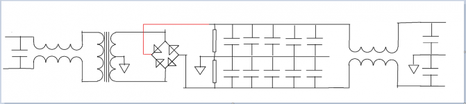
1. It is mandatory to filter power coming into transformer
2. Use appropriately sized transformer
3. Use a regular bridge rectifier
4. Use an array of parallel caps for main reservoir to slow down the main reservoirs transient response. (We do not want this part of the PSU responding to transients)
5. Use bleeders, fuses etc for safety during servicing, thermistors for slow start if needed etc
6. Use decoupling caps to ensure that the transient slows down before getting to main reservoir
7. If there is chance of noise coming in via a sibling winding, take care of it
8. If PSU unit is on the same board as load circuit. Use a filter between main reservoir and decoupling caps
.....
Circuit to follow,
.........Tom hope this helps
Looking at this model it becomes easy to see why the pi filter is there on many of the PSU PCBs on diyaudio. And also why there are those that sweat multiple paralleled caps (apart from cost savings, the issue is, how slow should one make the reservoir bank ?).
Attachments
Last edited:
................I asked because I seem to remember a drawing by mike on another thread sharing the opportunity of placing a resistor between Power and Main Audio grounds,..............
.............- to post 2941.............
I still don't know what you are talking about.
I see reference to 100r and 100 ohm.
..........of course 100,................. I'm anyway referring of - that - resistor between the two grounds. Is this relevant to what you were stating about the two grounds, or am I barking at the wrong tree?.................
Are you now referring to post1575? There is a 100r there.
the posts seem to me to be referring to different locations for different resistors.I'm keeping referring to
post 1575 of this thread (my post) and
post 2941 of
http://www.diyaudio.com/forums/solid-state/193923-simple-symetrical-amplifier-295.html#post3154084 .............
Leach and others show the Signal Ground connected to the Power Ground, but they add a resistor in this link to reduce the effect of a current loop where the Signal Ground has a second connection via the Main Audio Ground to the PSU Zero Volts.
That resistor between SG and PG in the amplifier PCB is for current attenuation in the loop.
Here is the phrase I think you are referring to
That resistor is clearly stated as being in the Main Audio Ground to Chassis connection.The new feature is the 100R resistor between the full earth of the casing and the star ground of the amp - got this from a TI application note that Sonny gave out in his TSSA implementation.
I think you are confused.
No wonder we have been around the track 5times for a 100m jog.
You have been wasting my time and extending this Thread with unnecessary posts.
I don't know the SSA, nor the TSSA and certainly cannot remember precise layouts nor component locations.
In future give a precise link that takes one directly to the item you want to talk about ! And learn how to copy a link location !
Last edited:
........
1. It is mandatory to filter power coming into transformer
2. Use appropriately sized transformer
3. Use a regular bridge rectifier
4. Use an array of parallel caps for main reservoir to slow down the main reservoirs transient response. (We do not want this part of the PSU responding to transients)
5. Use bleeders, fuses etc for safety during servicing, thermistors for slow start if needed etc
6. Use decoupling caps to ensure that the transient slows down before getting to main reservoir
7. If there is chance of noise coming in via a sibling winding, take care of it
8. If PSU unit is on the same board as load circuit. Use a filter between main reservoir and decoupling caps
.....
Circuit to follow,
.........Tom hope this helps
Some good advice and good observations mixed in with complete coddswallop.Looking at this model it becomes easy to see why the pi filter is there on many of the PSU PCBs on diyaudio. And also why there are those that sweat multiple paralleled caps (apart from cost savings, the issue is, how slow should one make the reservoir bank ?).
1. mandatory?
3. other rectifiers?
4. slow down the main reservoirs transient response?
. We do not want this part of the PSU responding to transients?
6. Use decoupling caps to ensure that the transient slows down?
8. Use a filter between main reservoir and decoupling?
Does anyone agree with "every" suggestion of OnAudio?
Yes.AndrewT said:Some good advice and good observations mixed in with complete coddswallop.
1. No, but sometimes it may be helpful.
2. Yes, but fairly obvious.
3. What is an irregular bridge rectifier? If you meant "don't bother with Schottky/soft turnoff etc." then say so.
4. No. An array of parallel caps could be 'faster' or 'slower' than a single cap, as it depends on the inductance. I can't see how 'faster' might be problem.
5. Yes.
6. Yes, if you are saying that decoupling needs to be properly done, near the point where the transient is developed.
7. Yes, although the term 'sibling winding' may be unclear. Rectifier spikes can hop from one secondary to another.
8. What sort of filter? A low value resistor might be sufficient.
DF,
you have two No and six conditional statements doubting the accuracy of what On stated.
I would interpret that as
No , not yes to the question
you have two No and six conditional statements doubting the accuracy of what On stated.
I would interpret that as
No , not yes to the question
Or do your mean "yes" there is someone that does agree among our hundred thousand Members?Does anyone agree with "every" suggestion of OnAudio?
AndrewT,
No. Two posts for same subject about proper grounding in order to lower noise floor. Mikelm is the author of the drawing on paper, then adopted by LazyCat.
You can think what you like.
You decided to answer and/or, viceversa, the same time issue is valid for me.
So?
I gave and I keep getting correct locations. It seems that you only are having this problem. But don't worry, in future we are NOT talking at all. You're too expert, right and wise for me. And even Ott is a lucky men to "follow" your advices (29 years ago). BTW, for just a moment I wondered how was that you didn't know of 1983 Ott's article when even a newbye like me (EE, anyway) was taught about it on diyaudio... ahh, I see, perhaps because it was in a SSA/TSSA thread...
EOF (End-of-file - Wikipedia, the free encyclopedia, it means End Of File, should you keep being unable to read links )
the posts seem to me to be referring to different locations for different resistors.
No. Two posts for same subject about proper grounding in order to lower noise floor. Mikelm is the author of the drawing on paper, then adopted by LazyCat.
I think you are confused.
You can think what you like.
No wonder we have been around the track 5times for a 100m jog.
You have been wasting my time and extending this Thread with unnecessary posts.
You decided to answer and/or, viceversa, the same time issue is valid for me.
I don't know the SSA, nor the TSSA and certainly cannot remember precise layouts nor component locations.
So?
In future give a precise link that takes one directly to the item you want to talk about ! And learn how to copy a link location !
I gave and I keep getting correct locations. It seems that you only are having this problem. But don't worry, in future we are NOT talking at all. You're too expert, right and wise for me. And even Ott is a lucky men to "follow" your advices (29 years ago). BTW, for just a moment I wondered how was that you didn't know of 1983 Ott's article when even a newbye like me (EE, anyway) was taught about it on diyaudio... ahh, I see, perhaps because it was in a SSA/TSSA thread...
EOF (End-of-file - Wikipedia, the free encyclopedia, it means End Of File, should you keep being unable to read links )
- Status
- This old topic is closed. If you want to reopen this topic, contact a moderator using the "Report Post" button.
- Home
- Amplifiers
- Power Supplies
- Power Supply Resevoir Size