have you heard of any recording done with an electric guitar without the signal going through at least a cabinet simulator? If you plan on replying "yeah for pickups with midi output" then it's not an electric guitar anymore, it's a midi controller.
Quite different choices of effects depending on the musician/producer, no not talking midi triggering or vocoder drive, but certainly Direct Injection of guitars and bass guitars is something not unknown in studios or live sound. That one was you excluded the DI thing, and it struck me weird, not mentioning the effects or post processing. Cab sims are still not the real thing, just production.
No, probably not. The reservoir size is set by LF requirements, where filtering has little effect.
One slight complication: if you have a really low resistance choke between reservoir and smoothing caps then you might be able to count the sum of the two as meeting LF requirements. The choke value would have to be such that at ripple frequency it blocked current but at LF it passed it. The danger then is a resonance somewhere between, so perhaps not a good idea.
One slight complication: if you have a really low resistance choke between reservoir and smoothing caps then you might be able to count the sum of the two as meeting LF requirements. The choke value would have to be such that at ripple frequency it blocked current but at LF it passed it. The danger then is a resonance somewhere between, so perhaps not a good idea.
No, probably not. The reservoir size is set by LF requirements, where filtering has little effect.
One slight complication: if you have a really low resistance choke between reservoir and smoothing caps then you might be able to count the sum of the two as meeting LF requirements. The choke value would have to be such that at ripple frequency it blocked current but at LF it passed it. The danger then is a resonance somewhere between, so perhaps not a good idea.
A resistor parallelled by a diode sort of fits that.
Thanks
-Antonio
How/come?
Grazie!
Just saying the resistor and 2nd stage capacitor forms a filter, but when higher current is demanded (low frequency) the diode conducts and the capacitors appear in parallel.
Ciao
-Antonio
Tom, does this help?
I havent Per-Unitised the secondary parameters, as it didnt fit on one page...
if you arent changing the VA rating at all, then the primary parameters wont change.
if you also want to change the VA rating, then I suggest you do two sets of base parameters - primary and secondary. you only need two base voltages (P & S), Pbase and wbase stay the same. then you can get Rp_PU & Lp_leak_PU referred to the primary, and Rs_PU & Ls_leak_PU referred to the secondary (provided).
to rescale for new VA and/or voltage, just specify your Pbase_new, Vbase_new then derive Zbase_new & Lbase_new.
Then the new R and L_leak is just R_pu*Zbase_new and L_leak*Lbase_new. voila.
Attachments
Just saying the resistor and 2nd stage capacitor forms a filter, but when higher current is demanded (low frequency) the diode conducts and the capacitors appear in parallel.
Ciao
-Antonio
So bypassing the resistor for high currents, right? Are there some quick and dirty sizing criteria? I've read 0,15 Ohm on each rail. What about the diode? (I assume one per resistor)
Thank you Antonio.
Ciao,
Stefano
So bypassing the resistor for high currents, right? Are there some quick and dirty sizing criteria? I've read 0,15 Ohm on each rail. What about the diode? (I assume one per resistor)
Stefano
Stefano,
I just mentioned this suggestion to add to the previous posts.
I havent actually done this and would have to think about all the implications before I really used or recommended it. I dont see anything particularly wrong with this it but its really just off the top head.
Sorry to have misled you.
-Antonio
No, a diode won't do it - it is not frequency sensitive. All a diode does is turn what you think is a smoothing cap into a second reservoir cap. A low value resistor would be better than a diode.
DF96
I agree but thats why I said "sort of fits". In response to Stefano's query I added the association with higher current and low frequency.
(to be clear I suggested a low value resistor and diode in parallel with it).
Thanks
-Antonio
On the original suggestion from Daniel that we insert a diode into the rail between distributed capacitors I have read that this is a problem with not just the chance of oscillation but that this could inject rf noise. Am I following this correctly? And if you added a diode and resistor in parallel how do you size that? A Shottky diode is supposed to be a fast diode and that is one of the things I remember reading was a problem with the rf injection. Someone who can answer this without going over my head would be nice.
On that reference to 60"s cars that goes without saying some of the time. My 1969 Z'28 with fast ratio steering didn't have that problem in the least. The thing to consider is that the bias ply tires of the time acted like a very slow charging capacitor and slowly reacted. The change to radial tires was like adding a much quicker circuit that also tracked the response inputs much better.....Didn't hurt to have Biltstein shocks, a lowered suspension, stiffer springs, anti-sway bars , 10 inches of radial tire on the front and 13" on the back, and other changes, but it was more than capable of keeping up with any Porsche or BMW of its time. 5 liters of pure fun with over 400 horsepower.
On that reference to 60"s cars that goes without saying some of the time. My 1969 Z'28 with fast ratio steering didn't have that problem in the least. The thing to consider is that the bias ply tires of the time acted like a very slow charging capacitor and slowly reacted. The change to radial tires was like adding a much quicker circuit that also tracked the response inputs much better.....Didn't hurt to have Biltstein shocks, a lowered suspension, stiffer springs, anti-sway bars , 10 inches of radial tire on the front and 13" on the back, and other changes, but it was more than capable of keeping up with any Porsche or BMW of its time. 5 liters of pure fun with over 400 horsepower.
Tom, does this help?
I havent Per-Unitised the secondary parameters, as it didnt fit on one page...
if you arent changing the VA rating at all, then the primary parameters wont change.
if you also want to change the VA rating, then I suggest you do two sets of base parameters - primary and secondary. you only need two base voltages (P & S), Pbase and wbase stay the same. then you can get Rp_PU & Lp_leak_PU referred to the primary, and Rs_PU & Ls_leak_PU referred to the secondary (provided).
to rescale for new VA and/or voltage, just specify your Pbase_new, Vbase_new then derive Zbase_new & Lbase_new.
Then the new R and L_leak is just R_pu*Zbase_new and L_leak*Lbase_new. voila.
Terry,
Thanks for all of that. I hope that I can figure out how to do the primary parameters.
But what if the input and output voltage levels are NOT being changed but the VA rating IS being changed? (i.e. just to get more current available) For example, that is what would have been needed to generate the data for the tables I posted.
Cheers,
Tom
Hey Tom, no worries. PU is an odd approach, but once you get used to it its very powerful. especially for DSP - once things are Per-Unitised (and normalised to whatever fixed-point number that corresponds to "1" eg 8192) equations all tend to be nicely conditioned, as lots of numbers are near 1.
you just change the relevant base quantites, before de-normalising:
if Vbase stays the same then dont change it; conversely if Pbase changes then change it. Then derive the remaining base parameters (Zbase ,Lbase and if you feel lucky, Cbase) before using those to de-normalise your PU values into absolute values. voila. when I have time, I'll whack up another MathCAD sheet showing this.
Cheers
Hey Tom, no worries. PU is an odd approach, but once you get used to it its very powerful. especially for DSP - once things are Per-Unitised (and normalised to whatever fixed-point number that corresponds to "1" eg 8192) equations all tend to be nicely conditioned, as lots of numbers are near 1.
you just change the relevant base quantites, before de-normalising:
if Vbase stays the same then dont change it; conversely if Pbase changes then change it. Then derive the remaining base parameters (Zbase ,Lbase and if you feel lucky, Cbase) before using those to de-normalise your PU values into absolute values. voila. when I have time, I'll whack up another MathCAD sheet showing this.
Cheers
Terry,
Thanks. I think I understand the basic idea. But I am missing something when it comes to implementation. For example, If Rs is normally 0.29 Ohms, then why is it 0.052 when I haven't changed any of my bases yet?
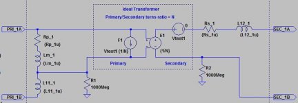
Here is what I have started with:
; Per-Unitized:
.param fb=60
.param Vsb=25.81
.param Ssb=120
.param Isb={Ssb/Vsb}
.param Zsb={Vsb*Vsb/Ssb}
.param Lsb={Zsb/(2*Pi*fb)}
.param Vpb={N*Vsb}
.param Spb={Ssb}
.param Zpb={Vpb*Vpb/Spb}
.param Lpb={Zpb/(2*Pi*fb)}
.param Rs_1u={Rs/Zsb}
.param L12_1u={L12/Lsb}
.param L11_1u={L11/Lpb}
.param Lm_1u={Lm/Lpb}
.param Rp_1u={Rp/Zpb}
for the attached schematic.
It runs, but has quite low output (when under load) when I try it with the bases unchanged from nominal. I also tried it with Vsb=36V and Ssb=360 VA, with 245 V 0-P input.
P.S. I think that the L11, Lm, and Rp are incorrect. The model has a slightly-different topology than most, for the primary.
Thanks again!
Tom
Attachments
Last edited:
Tom, you've got it.
yeah, get it running with the exact same bases first, playing spot-the-screwup is easier that way (isnt it funny how the easier something is, the more likely I am to screw it up the first time? I think its because we concentrate harder on the real tricky stuff).
If Rs is normally 0.29 Ohms, then why is it 0.052 when I haven't changed any of my bases yet?
read Rs_pu as 5.2%. I was being lazy when I did this worksheet, otherwise I should have expressed it as such.
the great thing about PU notation is its real easy to do a lot of calcs. for example if the primary and secondary copper loss are equal (and they probably ought to be if the windings occupy equal volume) then Rp = Rs*N^2, or in PU Rp_PU = Rs_PU
and if you use Omega_PU rather than F_PU, then there are no fixed constants - the toopies all vanish.
Cheers
Terry
- Status
- This old topic is closed. If you want to reopen this topic, contact a moderator using the "Report Post" button.
- Home
- Amplifiers
- Power Supplies
- Power Supply Resevoir Size