Thanks Frank,
the various transformer capacitances and the effects of the current harmonics generated in both the sec and pri windings plus the effects of the load/filter capacitances reflected thru the diode bridges - perhaps the SIMs just gets too complicated to include these other mechanisms?
For me, it's usually just a problem to find what values to use, and where to place them in the model. If I have that information, it's usually no problem to include it in the simulations. And the simulator doesn't have a problem with it, either way. It can simulate much more complex models than I have ever even attempted.
Out of curiosity, has anyone tried hooking up several batteries to form a power supply for an amplifier? For instance 3 or 4 motorcycle batteries per rail, to a known working amplifier to see if there is an audible difference. Something in that direction to be able to say that a more perfect power supply is worth the work and or effort.
Krisfr,
I think if you look here on one or more forums that has been talked about. I don't think that a battery has been found to be a perfect power source either as they have their own electrical inductance and capacitance parameters to think about. Do a search, I know I have seen multiple references to this.
I think if you look here on one or more forums that has been talked about. I don't think that a battery has been found to be a perfect power source either as they have their own electrical inductance and capacitance parameters to think about. Do a search, I know I have seen multiple references to this.
yes, if for no other reason than large batteries make it really, really easy to wire up gigantic loops.
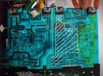
here's a good example of large loops in a PCB:
the EL cap placement means they reduce the loop area by very little - only the bit above them. At higher frequencies where the cap ESL becomes significant, the loop area is as shown
here's a good example of large loops in a PCB:
the EL cap placement means they reduce the loop area by very little - only the bit above them. At higher frequencies where the cap ESL becomes significant, the loop area is as shown
Attachments
Last edited:
Terry, do parallel caps at power supply boards reduce both overall loss and inductance similar to inductors in parallel?The EL cap placement means they reduce the loop area by very little - only the bit above them. At higher frequencies where the cap ESL becomes significant, the loop area is as shown
The performance is nice. The idea seems to improve standard caps.
Also, I'm not quite familiar with how to assure filtering occurs, since the worlds best specs capacitors at power boards tend to send noise signal as intact as possible rather than flattening/ruining the noise signal like standard/econo caps do better and there's quite the difference in bass between those two choices, all of which favors the caps with the inferior specs and none of which favors the caps with the best specs (if used on linear unregulated power boards).
The only place I've been able to use the high zoot (excellent specs) capacitors as an enhancement, is as a shield for the amplifier board, where we do probably want to send the noise, intact, somewhere else. That actually favors low ESR varieties as much more important than low inductance varieties.
And, the wide body (big size) low inductance varieties are prone to having the amp sound as bad or worse than a cheap standard cap used at the amp board. Except for caps in parallel, I can't seem to implement low inductance caps to do any good anywhere in an audio amp as some fairly powerful caveats seem to accompany the wide body low inductance specialty caps, especially poor results with those that aren't low ESR.
P.S.
My testing capacity is crude; however, those caps that succeed best in a contest of peers, as an output cap and other signal duties, tend to be the excellent specs varieties (mainly low ESR), which, of course work great on amplifier board power circuit. But that variety are very weird on power boards and there's no bass. Help?
Last edited:
Daniel,
look at the PCB layout above. see the highlighted loops? pick one - lets say the white loop.
Break the white loop into 3 separate areas:
1 - the area above the electrolytics (up to the rectifier)
2 - the area directly beneath the electrolytics
3 - the area below the electrolytics (down to the O/P transistor)
these three areas correspond to three sets of stray inductance (which is proportional to loop area):
L1 - Inductance between the caps & rectifier
L2 - Inductance between the caps themselves
L3 - inductance between the caps & the O/P transistor
Its not too hard to physically calculate these inductances (F.E. Terman's Radio Engineers Handbook has pages of relevant formulae), nor is it hard to measure them given a blank PCB.
But without calculating or measuring anything, we can make some observations:
1. L3 >> L2 & L1 - the bulk of the loop area is between the electrolytics and the O/P transistor. It doesnt matter what you do to/with the capacitors to reduce ESL if this loop remains untouched. Its the 400lb gorilla thats defacating on the carpet and kicking holes in the walls during subjective listening tests.
2. think about the mutual inductance with the 1uH air-core output inductor - thats not going to help now, is it (hopefully they are at least orthogonal).
3. L2 adds to the capacitor ESL (and is probably bigger).
4. L1 doesnt really stop at the rectifier - the inductance (loop area) of the long dangly wires to the transformer need to be included too (although if cable tied together this is still a lot less than area 3).
A DC bus is supposed to be exactly that; a sizeable chunk of this thread has been demonstrating that good DC bus layout is important. However many of them are far from low impedance, and as shown there can be all manner of exciting inductive couplings present. "normal" wiring and PCB layout practises in audio amplifiers are horrendously bad, for no apparent reason I can see (other than applied misunderstanding).
So before you can attempt to compare the effects of various caps you really need to:
- ensure all xfmr wiring is short & tightly twisted
- ensure the DC bus PCB layout is extremely low inductance (regardless of how you do it, no single-sided layout will ever be good in this regard)
I'd also make sure the output leads are tightly twisted, and ensure the L,R output inductors are orthogonal and as far away as possible from each other and the AC input (this has the extra advantage of increasing immunity to external fields).
and then I'd measure the impedance of the DC bus (seen from the O/P transistor) to see how good my cap bank was. its not that hard to keep the impedance in the mOhm range up to a few MHz, and with careful design that can extend to a few hundred MHz.
Thank you! That was totally understandable and contains some good tips as well!
The other question was, although the loss of series filters and cables could increase the need of a larger power supply reservoir, what sort of parallel filters (other than caps, capmulti, kmulti, regs) could decrease the need of large power supply reservoir size?
The other question was, although the loss of series filters and cables could increase the need of a larger power supply reservoir, what sort of parallel filters (other than caps, capmulti, kmulti, regs) could decrease the need of large power supply reservoir size?
danielwritesbac,
I have been trying to keep up with this thread and I must admit that much of the technical discussion goes over my head. But at the same time when you questions whether any other type of filtering would reduce the requirements of the power capacitors I just don't follow that. There does obviously seem to be a balance between the allowable maximum voltage for a particular circuit with particular devices staying within the SOA and the required capacitor reservoir size to limit to some agreed upon % of ripple currents. What am I missing here that changes that? If you have a transformer with sufficient voltage output, high enough VA rating, and a minimum capacitance, how is that affected by any additional non-capacitance type of filtering?
Steven
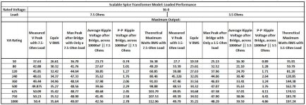
The table in my last post had the theoretical maximum output power for a single sine tone, i.e. it took the average ripple minus half the p-p ripple voltage and assumed that was a sine's maximum-possible peak voltage. So it divided by sqrt(2) to get the RMS voltage then used V-squared over R to get power. Consequently, those values appeared to be very-conservatively small.
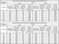
The attached similar tables give the theoretical maximum output power assuming a square wave instead of a sine wave. For a square wave, the peak value IS the RMS value. So the theoretical maximum power shown in these tables really is around the maximum usable power (for cases where the transformer could support it), but an amp could be well into clipping at the levels shown, since there often needs to be four or five volts headroom between signal and bottom of ripple.
The scalable spice transformer model is great, because I can now automatically sweep parameters such as VA rating, and Volts RMS rating.
NOTE: 7.5 Ohms and 3.5 Ohms are the average impedances seen across the transformer's output terminals, during charging pulses, with 8 and 4 Ohm loads. Those impedances include the whole load, including the amplifier, not just the output resistor. Since the measurement setup for these tables doesn't include an amplifier, I used 7.5 and 3.5 Ohms to get the voltages but used 8 Ohms and 4 Ohms to calculate the power delivered to the load.
Oh, the reason I started making these tables was initially just to test the new scalable transformer model. Then I also thought they would be nice to have, to see if a particular power/load/VA combination was "reasonable" to try to simulate, to use as a data point for the required capacitance per amp of output current.
I was going to post all of the spice files for everything so far, but it's getting late so it will have to be tomorrow.
Cheers,
Tom
Attachments
Last edited:
danielwritesbac, I have been trying to keep up with this thread and I must admit that much of the technical discussion goes over my head. But at the same time when you questions whether any other type of filtering would reduce the requirements of the power capacitors I just don't follow that. There does obviously seem to be a balance between the allowable maximum voltage for a particular circuit with particular devices staying within the SOA and the required capacitor reservoir size to limit to some agreed upon % of ripple currents. What am I missing here that changes that? If you have a transformer with sufficient voltage output, high enough VA rating, and a minimum capacitance, how is that affected by any additional non-capacitance type of filtering? Steven
For an example of huge capacitance easily defeated:
Let's grab an old style half wave car battery charger (he say "Narrrr") hook it up to the car battery and measure the AC voltage present. It is about 6v added peak noise (total output ~18v of garbage). Any audio equipment attached to that gets "Narrr" noise. That's a great example of what capacitance doesn't do. And, using a bigger transformer won't help either. And the bass is insufficiently supported while the charger is on, thus it seems that even the biggest capacitance is insufficient whilst charging. Near identical conditions occur in audio amplifier power supplies--except milder than this big example. I totally guess that the dramatic bass differences between different model caps of same value is a closely related question.
Result: Some critical bit of design is missing. Since there's some things capacitance doesn't do, I guess it is a parallel filter of some sort that might help. But I haven't found out yet.
And:
I'd like to know whether this is my imagination or real, so I put the question to Tom and Terry and I'm willing to accept any answer they might give.
Else:
If they say "no" then I'm perfectly willing to assume that some caps are simply harder to charge than others and I had attempted to do it with a "borderline" too small transformer, thus going definitely too small when pushing the more stubborn models of caps with the totally expected consequences that the bass went missing. Although that's the most plausible answer, its only useful if its the real answer.
Which is the most likely case? I don't know, so I'm asking.
Charger plus battery has no capacitance. How can that be "a great example of what capacitance doesn't do"? It is an example of what 'no capacitance' does do!danielwritesbac said:Let's grab an old style half wave car battery charger (he say "Narrrr") hook it up to the car battery and measure the AC voltage present. It is about 6v added peak noise (total output ~18v of garbage). Any audio equipment attached to that gets "Narrr" noise. That's a great example of what capacitance doesn't do.
So, paralleling a capacitor fixes that situation?Charger plus battery has no capacitance. How can that be "a great example of what capacitance doesn't do"? It is an example of what 'no capacitance' does do!
In this case, the parallel filter I was looking for is simply adding more capacitance?
Not 'more capacitance', but 'some capacitance'. However, it will need a lot because a lead-acid battery has quite a low impedance. Ideally you would need a battery with 4 terminals so the voltage drop across the terminal contact resistance caused by charging pulses does not go to the audio circuit.
Why bring batteries into the discussion? A lead-acid battery and a big electrolytic are not the same thing, even though they both use electrolysis. They use electrolysis for different reasons: one to store charge by migrating ions and depositing metal on plates, the other to build an insulating dielectric layer.
Why bring batteries into the discussion? A lead-acid battery and a big electrolytic are not the same thing, even though they both use electrolysis. They use electrolysis for different reasons: one to store charge by migrating ions and depositing metal on plates, the other to build an insulating dielectric layer.
")
Not 'more capacitance', but 'some capacitance'. However, it will need a lot because a lead-acid battery has quite a low impedance. Ideally you would need a battery with 4 terminals so the voltage drop across the terminal contact resistance caused by charging pulses does not go to the audio circuit.
Why bring batteries into the discussion? A lead-acid battery and a big electrolytic are not the same thing, even though they both use electrolysis. They use electrolysis for different reasons: one to store charge by migrating ions and depositing metal on plates, the other to build an insulating dielectric layer.
Well, I did notice that some electrolytics work better for smoothing than others, and some are practically useless for smoothing, such as the car battery, which was an overly extreme example.
However, there's also some caps that can transport a signal extremely well and perhaps intact, yet that same cap doesn't work well on the power board. I'd sure like some "grip" on that problem so I can more reliably select capacitors. It is rather disheartening to have done an excellent job on the power board assembly and with excellent quality parts, only to discover that the job didn't get done. So far, adding more capacitance is not the effective fix; but changing the model of capacitor does it no matter if you increased the capacitance or not. I sure can't explain it, but I wish I could predict it a bit better.
are you sure you know what you are talking about?Well, I did notice that some electrolytics work better for smoothing than others, ....................... I sure can't explain it, but I wish I could predict it a bit better.
Creating a DC supply from AC is easy.
Transformer, if the AC voltage is not right, + rectifier and smoothing capacitor. That is all that is needed. Miss any of these out and you won't get the correct DC voltage as the input to any charger.
You need to wise up by doing the research.
Well, I did notice that some electrolytics work better for smoothing than others, and some are practically useless for smoothing, such as the car battery, which was an overly extreme example.
However, there's also some caps that can transport a signal extremely well and perhaps intact, yet that same cap doesn't work well on the power board. I'd sure like some "grip" on that problem so I can more reliably select capacitors. It is rather disheartening to have done an excellent job on the power board assembly and with excellent quality parts, only to discover that the job didn't get done. So far, adding more capacitance is not the effective fix; but changing the model of capacitor does it no matter if you increased the capacitance or not. I sure can't explain it, but I wish I could predict it a bit better.
There are only a few variables. Unfortunately, each one multiplies the chances of us not knowing whether or not you have comparable or analytical setups by infinity, or in some cases infinity squared.
As Terry and others have mentioned, it could be challenging, even under rigorously-controlled conditions, to know the true causes of some effects. (But here's a tidbit for your own mental toolbox: "Current does NOT follow the path of least resistance (or impedance). It follows ALL paths, in inverse proportion to their resistances (impedances)." Filtering is different than transmitting input or output, because with filtering the signal has two paths to take, rather than just one.)
However, in case it's something that is easily explainable and measurable, such as the capacitors' ESRs or inductances, you could download the spice model I posted and do things like: automatically plot a series of frequency-responses, one for each ESR in a sequence you can define. You could plot the frequency response for any range of steps of variation of _ANY_ parameter, anywhere in the circuit! If there are correlations with certain frequency ranges, you will immediately SEE them, as the multiple plots (of ratio of output vs input amplitudes, over frequency) all take form on the same axes, right before your eyes.
Interested in distortion? It's almost as easy. You can tell anything at all in the whole schematic, including any parasitics you choose to insert, to vary over whatever range of steps you desire, and use a sine wave as the input, and you can receive a THD number for each step of the variation that you commanded. The only difference from above is that the THD numbers get placed into a text file that you then have to open, after the automatic sequence of stepped variations has finished running.
If you could do something like that, what would be the first thing you would try looking at?
Category error. A car battery is not an example of an electrolytic, extreme or otherwise.danielwritesbac said:Well, I did notice that some electrolytics work better for smoothing than others, and some are practically useless for smoothing, such as the car battery, which was an overly extreme example.
Capacitor ESR, and possibly inductance, will play a role. Capacitor nonlinearity might play a role as it could cause hum IM.
- Status
- This old topic is closed. If you want to reopen this topic, contact a moderator using the "Report Post" button.
- Home
- Amplifiers
- Power Supplies
- Power Supply Resevoir Size