Hi Everyone.
I started a thread in parts about capacitor choices for the power supplies I'm building for my new amplifier. I'm planning on using the Aussie Amplifier HPA-nxV500 R2 amplifier boards. I'm going to have separate dual mono supplies for the input & output, but all in the same large chasis. The required outut voltage is around 78 volts. I already have 2 - 1000VA 58-58 and 2 - 250VA 58-58 toroids that I bought from someone at a good price for both supplies. He bought them a couple of years ago for a project that never happened and they've never been used. That would make the voltage 81-82 on each rail which should be no problem. I've been looking over and reading all the posts on power supplies as well as many online articles. I see in most Class A amps, inductors are used between the caps to reduce noise. I was wondering if this makes an audible difference and why you don't see it in any of the class AB amps. I originally planned on using 8-Panasonic 12,000 uF 100v caps for each channel for the output and 6 of the same for each channel for the input. I was just wondering if adding inductors was something worth considering, and if the amount of capacitance I'm using would be enough to prevent any oscillations from the inductors? Also, do the inductors cause the output voltage to decrease? And how do you determine the proper value for the inductors. Thanks in advance for any help that can be offered.
Best Wishes,
Bob
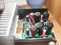
A wire-wound resistor is as far as I will go for a class AB supply. Like Andrew says it should be between the capacitor stages. C-R(L)-C-C-Cfilm. In this circuit, the coils in the yellow rectangles are resistors. I needed ~100mOhms. 6ft of 22Gauge magnet wire is close enough, and cheaper than a power resistor since I had plenty of scrap magnet wire and stand-offs. It is wound around 6-32 size typical aluminum stand-off. As for inductance, it is negligent. Also it is important to seperate the return currents from the different capacitor stages. Each capacitor stage should have it's own return path to the star ground point so as not to mix power supply AC input currents with speaker return currents...(Bbbzbbzbzbbzbzzz)
It is wound around 6-32 size typical aluminum stand-off. As for inductance, it is negligent. Also it is important to seperate the return currents from the different capacitor stages. Each capacitor stage should have it's own return path to the star ground point so as not to mix power supply AC input currents with speaker return currents...(Bbbzbbzbzbbzbzzz)Attachments
Last edited:
Thanks for the suggestions. I was wondering how much of a voltage drop the resistors would cause as opposed to inductors. Would something like 5 watt Mills wirewound resisters be OK. Also, how do I determine the proper ohms value to use. In a wiring diagram I saw in an older thread, it shows just as you said with an inductor after the first cap on both pos. & neg rails and lots of uF after the inductor and a film and bleeder resistor at the end. But it showed all the 0 Volt in center wired together along the enire string. So how would I separate the front and rear sections to ground. I'll actually end up with 4 separate supplies ( 2 mono lower current supplies for the input and 2 mono high current supplies for the output. I'd want to try to keep the voltage into the boards at least 78 volts for all 4. Wouldn't the resister approach cause a much greater voltage drop. I would need either 8 inductors or 8 resistors. Would it make more sense to do this just for the lower current input stage that might be more sensitive to noise, or would all 4 supplies be the best approach. I'm already nervous about how to ground all of this for no bzzzz or hum with 4 power supplies in the case. Would everything go through just one ground loop breaker circuit (bridge, resistor, cap) tied to earth ground? So many questions. While I can read a schematic and have a basic idea of what's going on, I don't have the knowledge to design my own circuits. But I love getting out the soldering iron and building a case and stuff like that. And when I started the rebuild of an old Hafler DH-101 preamp about 2 years ago, I started reading tons of old threads and books on audio design & theory. Some I understand, and some I'm still trying to figure out. The preamp came out great and I could hear a major improvement. I have an unmodded one and it's like night & day. The only change I might try in the future is either a Salas low voltage regulator based supply or one based around the super regulators. Of course it took me over 2 years to finish it. But I'm patient. I built a pair of mono Leach amplifiers around 35 years ago. That took me over 3 years. I remember how great they sounded. I gave them away about 15 years ago when we moved (they were really heavy) and now I'm looking forward to building something again of at least equal or better quality. The amp modules are not DIY as they come all finished, but all the rest is, and that's enough for me at this stage. Thanks Again for all the help. Very, Very Much Appreciated.
Best Wishes,
Bob
Best Wishes,
Bob
Use PSUdII to model your supply proposals.
Compare zero L and Zero R to a little L and/or a little R between the capacitance.
The results only show the mains' ripple attenuation. There is also the harmonics attenuation that is MUCH greater and should not be thrown away just because some say you will get rail sag.
Using 0r1 in the rail gives a bit of volts drop due to continuous current demand, but almost no volts drop due to transient current demand. A little uH will also cause a tiny Volts drop in the supply rail, but less than using R alone. The big advantage to using uH in the rail is the attenuation of the harmonics and especially the spikes coming from the mains and from the rectifiers switching off suddenly.
It is so easy and cheap to wind 50 to 100 turns of 0.6mm diameter enameled copper on a 10mm former between cheeks set 6mm apart, that I now adopt this for all my assemblies. The only variable is the wire diameter and I have a selection to suit the continuous current demand.
Hi Andrew Thanks for explaining things clearly. I went to the site of PSD2 to try some simulations, but the instructions indicate it only works with older versions of Windows. All my computers have Windows 7 64 bit. Can I install it on my computers, or will it mess things up?. I don't have access to any cmputers with Windows 95, 98, or NT. I could borrow a neighbors laptop with Windows XP, but I wouldn't want to install the software if it could mess up his laptop, as XP is not mentioned as one of the accepted platforms. Thanks Again, Bob
most of 32bit apps can run on 64bit system.
if the program can't run in win7, try to change its compability, by:
~ righ click on the *.exe file,
~ Properties >> Compability >>
~ check on "Run this program in compability mode for:"
~ chose one
~ click apply/OK.
try it,,
if the program can't run in win7, try to change its compability, by:
~ righ click on the *.exe file,
~ Properties >> Compability >>
~ check on "Run this program in compability mode for:"
~ chose one
~ click apply/OK.
try it,,
Last edited:
Hi Everyone,
I recently went to a meeting of a local audio club and was discussing my planned amplifier with some of the members. I mentioned the CLC supply and they seemed to feel it would only be necessary for the lower current front end supply.
Today, one of the members emailed me a picture of a layout he recommends using some parts I had on hand (except for the inductors).
http://www.diyaudio.com/forums/gallery/showphoto.php/photo/7537
I attached the picture, but I think there is no thumnail. But it opens if you click the link.
I thought I would post it here to see what your thoughts are on the values and layout.
He also stated that I would need to shield the inductors from all circuits and that they should bu mounted in a separate shielded box at right angles to each other and at least 3 - 4 inches apart from each other. Is that actually necessary? And if so, how would I shield them?
Thanks Again for the help & suggestions.
Best Wishes,
Bob
Last edited:
First sentence is true. Second sentence is false, as it guarantees the very thing you should be avoiding by injecting charging pulses into the star ground.CBS240 said:Also it is important to seperate the return currents from the different capacitor stages. Each capacitor stage should have it's own return path to the star ground point so as not to mix power supply AC input currents with speaker return currents.
The return path for the first cap should not go to the star point but to the bridge/transformer. The return path for the second cap can go to the star point. Then link the ground sides of the two caps together. The result is that the star ground only gets a little smooth ripple current into it instead of big narrow charging pulses.
I am puzzled why people keep making this mistake. There must be a website somewhere which encourages it.
Hi DF96. Thanks for the reply. So the first 2 caps should have their 0 v separate from the ones after the inductor with both returned to ground separately through the loop breaker? The copper plate that he's showing should only be connected to the 4 caps after the Inductor? I received another email with a schematic, and it showes the same setup as the first with a 2.2 mH inductor recommended, but all wiring exactly as in the first picture sent. I guess that's how many people think it should be wired.
Do the values they put in for the inductors make sense? Also, I originally thought I could mount the inductors in my case but they say no. Their would be 4 inductors total. I attached a sketch of my planned layout for the case with the inductors mounted inside. If I mounted them in a box outside the case, I would have to run wires at least 5-6 inches long to the caps from that box.
Case Layout Sketch - My Photo Gallery
I would mount the inductors one over the other in a stacK of 2 on each side of the transformer, about 1.5 inches from the transformers. The 2 panels separating the center mounted supplies are copper covered with a very, very thin mumetal tape to give some shielding for the boards. Since the transformers are mounted in a stack of 2 horizontally, I thought I would mount the inductors vertically. Would this cause all the problems with interference they caution me about? I have some copper plate & mumetal tape left and could mount a piece halhway between the inductors and transformers as well as on the platforms between the inductors if that would help. Thanks Again.
Best Wishes,
Bob
First sentence is true. Second sentence is false, as it guarantees the very thing you should be avoiding by injecting charging pulses into the star ground.
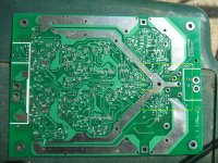
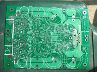
Yes you are correct, I worded it to simply, bad discription. A 'star on star' will keep those currents seperated, as in the PCB in the pics... Apologize for the confusion.
Attachments
Hello,
I am happy to read something on chokes again. In the past i did have a class A with 1.5A current with plus minus and earth. Now i wanna make a choke input powerr supply for a virtue amp ( class D ) for my audio video set up.
It has a single rail just plus and earth, dc tension about 25 volts, 600 ma current draw from the circuit.
I have a 30 volts ac transformer, 2 chokes 100mh, 1.3A 1.3ohm. Wanna use a bleeder that will take about 250 ma so it will be choke input all the time.
The 30 volts wire from the transformer are short, i wanna solder them directly to the rectifier bridge, from the bridge there is a few inches wire to the first choke, from the first choke a few inches to the first cap ( not sure about the capacity yet ), then about 5 inches to the second choke and a few inches to the last cap ( in the outboard power supply )
From the last cap there is about 10 15 inches to the amp itself.
The bleeder will be attached at the first cap. The negative side from the first cap will '' return '' directly to the rectifier. The '''negative '' side from the bleeder as well or should it be connected to the negative terminal of the first cap?
From this'' meeting point '' at the rectifier there will be a connection to the negative side of the second cap and from the nergative side of this cap there will be the connection with the power amp itself.
I did do a little test to check the voltage with a total current around1.1A. The chokes are dead quiete ( potted profesionel ones from Bourdereau from the sixties) The amp is on the way so i just like to have some advice.
Many thanks in advance. Will post a picture later.
Sincere greetings and many thanks for sharing your ideas, Edward
No, you want the 'meeting' point here to be near the first cap, not near the rectifier. If you want to think of it as a single connection then it goes: rectifier (or CT) to first cap ground, first cap ground to second cap ground, second cap ground to circuit ground (or star point). Think where the currents go, and assume that every connection is a resistor (it is a resistor!) so it will cause a voltage drop.eduard said:From this'' meeting point '' at the rectifier there will be a connection to the negative side of the second cap and from the nergative side of this cap there will be the connection with the power amp itself.
The bleeder resistor connections should normally 'mirror' each other i.e. put it directly across a cap. It doesn't matter too much which cap it is, but you don't want it to inject dirt into an otherwise clean point.
I was searching around online and I came across this schematic for an Aleph CLC power supply clone board being sold.
Web Sample CLC - My Photo Gallery
This is pretty much the exact same schematic that I was sent in todays email. It looks like he got it off the internet. I changed it slightly to this.
CLC websample2 - My Photo Gallery
Would this actually be the correct way to wire this with each section coming back separately to the loop breaker that's connected to earth ground?
Best Wishes,
Bob
- Status
- This old topic is closed. If you want to reopen this topic, contact a moderator using the "Report Post" button.
- Home
- Amplifiers
- Power Supplies
- Inductors in Power Supplies