Hello Andrew,
Maybe there was a little short circuit in the rectifier board because parts were to close and they did move a tiny bit because the leads from the transformer are very sturdy. It looks like one of the wires did touch one of the 4 small heatsinks which are directly connected to the diodes. The heatsinks are of course not connected to each other.
Because the variac was at the very beginning of the scale i assume it cannot be one of the diodes did break down because of to much current?
A big bridge can be soldered directly to the transformer secondary wires and work with just a small heatsink ar attached to a small alumium piece . ( after all we have loads of alumium thrown away at work).
Hoping to get my amp soon so i can connect it, Edward
Hello,
Today i had a half day of because i had to go hospital to eat radioctive pancake to test functioning of my stomach so i had some time to do some diy.
I did wire the switch and the fuse holder. A 4 ampere slow blow fuse did not break down so i guess the current at inrush isn't that big and somehow a bit reduced by the choke input. The load now is a big wirewound that will take as much as the amplifier which will arrive soon.
The amp itself has a slowstart function at the entrance of the dc plug (24-30 volts) . At the circuit there is another 27000uf cap.
Maybe the value of the fuse can be a bit lower. I can always check once i connect the amp itself.
Maybe will make a new bridge with the 4 mur860 or maybe go for one bridge rectifier . So much easier. I can change a bridge in 30 minutes. Maybe add some snubbers.
I remember in the L'Audiophile Nemesis amp they had a 1uf cap across the secondary winding of the power supply. I can try a similar thing but i guess every transformer will have an optimum value for that cap.
Sincere greetings, Edward
pancake
Yummy (though it's called radio opaque)
You should have tried the chocolate specialty that's used for galbladder tests, aka the big squeeze.
Hi.
im building a Holton nxV300r2 and are gonna put everything in one box approx 17" x 17" x 4" so space is a "absolute" factor
Im gonna use a CLC chain consisting of:
output section (for each channel)
500va - MSR1560G - 22000uf - 2,2mh (air 0,63ohm) - 15000uf
input section (for each channel)
50va - MUR860G - 15000uf - 10mh (cored 0,5ohm) - 6800uf
Since space is limited i prob. need to mount the inductors quite narrow, the layout as of today gives me only about 6" x 6" x 3,5" in for the inductors. (there will be 4 of each inductor)
The inductors are about 2" dia and 1" (air) and 2" (cored).
I could physically place all inductors in the pace i have but it will not be iaw "crossovers rules" ex: Placement of coils in crossover networks
Q1
How critical would you consider location ,placement and direction of the
inductors are? (with 8 inductors there many variables)
Q2
I have thought of a setup of 4 inductors placed the same way in a square of 2 rows, and a set of inductors on top of these turned 90deg to the bottom layer but all of these 4 the same way (all of this to make it fit in the limited space)
Then i could put a double layer of MUmetal between all 4 inductors from top to bottom , would you consider this a fairly god solution?
Thanks
Last edited:
Pell,
reduce your inductor values by a factor of 10.
Swap the capacitance around.
Big smoothing after the inductor.
High ripple capacity smoothing before the inductor.
Ok
but when trying this out in PSU designer i end up with much more ripple voltage at the load, just by reducing 2,2mH to 1mH i go from 65mV to 115mV (same load 3A and same inductor resistance 630mohm)
Or is it something i have missed here?
P.
Last edited:
Pellesmil,
Now put a fluctuating load on the PSU and see what happens,
vac
Yes tried a 3a - 100ma load and the ripple is much lower, with a suggested 1/10 of 2,2mh inductor i end up with 5,5mv ripple.
Hello,
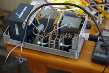
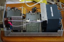
I did finish my outboard power supply for my soon to arrive virtue sensation amp. A 3A slow blow fuse isn't protesting diring switch on so i guess i will leave it as it is. Maybe will put some mu metal sheets around the chokes and have to make a cover for the complete supply. So far every metal piece i i did use is aluminum. The front will probably be stainless brushed steel and the cover aluminium or stainless steel as well. Will have to perforate it pretty well because the transformer is getting warm maybe because of dc on the line. Can attach a dc blocker to the back of the chassis.
The amp did sort the los angeles airport so it is getting closer.
Kind greetings, Edward
Attachments
- Status
- This old topic is closed. If you want to reopen this topic, contact a moderator using the "Report Post" button.
- Home
- Amplifiers
- Power Supplies
- Inductors in Power Supplies