Here is the circuit adapted to feed from the cathodes with minimal audio interference, and a modified BOM (2N2905 ~= 2N2904).
At a nominal 80mA cathode current, the green (center) LED is lit from ~75mA to 85mA.
The percentage would remain similar at other currents
At a nominal 80mA cathode current, the green (center) LED is lit from ~75mA to 85mA.
The percentage would remain similar at other currents
Attachments

Thanks for this second design effort, Elvee.
I'm going to do a test-build.
I got hung up for a day or so, as my OS went down.
I have to reinstall Linux, and all the drivers.
I have one more question:
If I get a hold of a Schottky diode,
can I just drop it in where it was before in this new circuit, and get tighter response,
or are there necessary adjustments that have to be made?

Great this is awesome!
Thanks for the help!
I will report back after I brave the snow and hail
to see if I can find a Schottky diode!
back soon, maybe a couple of days on this.
Thanks for the help!
I will report back after I brave the snow and hail
to see if I can find a Schottky diode!
back soon, maybe a couple of days on this.
Back again!
I built a prototype version.
After trying 290volts, and a 12K as a PS feed resistor, that quickly overheated (4watts thru a 2 watt resistor oops).
It seemed to work but two LEDs fried.
More cautiously, I tried a 5w 1k resistor and a 30 volt supply,
after replacing two LEDs.
It seemed to work, except the middle Green LED didn't come on.
I tried substituting the schottky diode in for the 30v zener I had, but it had no effect.
I tried bypassing the diode in my diagram, and just connecting straight through, and voila! the Green LED lit up.
I had mocked up 4.4 R for each of the reds by putting 2.2Rs in series on each side (green 5 watt resistors).
These were supposed to be 5.8 so I inserted another 2 ohm resistor, which seemed to bring the reds closer to the middle.
In the end I left it at 6.4 ohms each side.
The sensitivity is as follows:
Red lights dim out at about +- .2volts difference (spread of .4v).
Green light comes on nicely, and the overlap is such that:
Green and one Red come on equally bright around +- .5 volts.
(see photos).
Trying my hand with a volume pot wired between a +- 5v supply and the tap and ground used as left and right comparison (-5 to +5 v spread).
I was able to dial in within 0.2 volts using the lights alone.
The basic problem is that the Reds are out and the green is on, for from about -0.2v to +0.2v. And you could land anywhere in there and think the voltages (and currents) were balanced.
With my projected Self-biased Push-pull output stage (2 6L6GC Idling at about 40 mA each),
and a 1.5k Cathode resistor, 40mA x 1K5 = 60V on the resistor, (Bias voltage).
Now an error of +- 1v is :
61v = 40.6 mA,
59v = 39.3 mA,
= about a 1mA difference possible.
With the accuracy of the indicator at +- 0.2v,
I am well within one mA of balanced current through each tube.
The +- 0.2 v is not so bad in this case.
Still, there are some disturbing side-effects for the circuit:
There are points where I turn the offset voltage imbalance,
and strange things happen, like all three tubes light up at slightly less than half-brightness!.
Its not as though one would mistakenly mis-bias the tubes,
because the bright Green light keeps you in the zone,
if you are paying attention.
Still the circuit seems a bit jerky in its responses and the behaviour of the three LEDs.
Do you have any comments?
Attachments


The test circuit looks more or less like this:
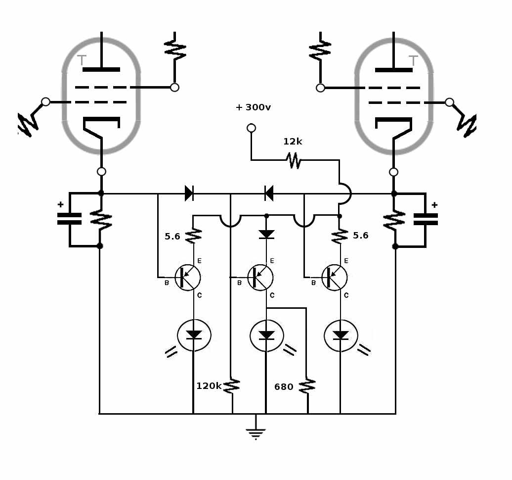
only substitute a 30v supply and a 1k (5w) resistor to power it.
Also take out the diode above the middle transistor and sub in a straight wire.
The 5.6 ohm resistors are now about 6.4, for no reason other than thats what I had on hand to slap together.
What happened was I failed to use the latest circuit posted by Elvee,
and didn't notice until after I had soldered it...Doh!
Attachments

Last edited:
After trying 290volts, and a 12K as a PS feed resistor, that quickly overheated (4watts thru a 2 watt resistor oops).
It seemed to work but two LEDs fried.
That shoud not be possible, since the current is inherently limited to 290/12=24mA, too small to fry any LED.
Something must have been wrong, or the LEDs reverse-connected.
If there are flying wires here and there, there could be a VHF oscillationThere are points where I turn the offset voltage imbalance,
and strange things happen, like all three tubes light up at slightly less than half-brightness!.
Also, if the difference voltage exceeds the Vbe breakdown voltage (~7V), the behavior could become erratic.Its not as though one would mistakenly mis-bias the tubes,
because the bright Green light keeps you in the zone,
if you are paying attention.
Still the circuit seems a bit jerky in its responses and the behaviour of the three LEDs.
Do you have any comments?
I breadboarded the circuit to make sure there were no unforeseen issues, and it worked as expected, which comes as no surprise, since it is very simple and highly simulable.
See pics for various ΔVin conditions.
Tail current=10mA, schottky=BAT43, emitter resistors=5.6Ω diodes=1N4007, transistors=2N2905
If the transistor breakdown is a problem, diodes can be added in series with the bases of all three transistors
Attachments


That shoud not be possible, since the current is inherently limited to 290/12=24mA, too small to fry any LED.
Something must have been wrong, or the LEDs reverse-connected.
Read over what you just wrote:
290 v / 12,000 = 24mA yes.
290V x .024A = 7 WATTS. - it was a 2 watt resistor that fried initially.
I noticed that your transistors are huge metal cans,If there are flying wires here and there, there could be a VHF oscillation
Also, if the difference voltage exceeds the Vbe breakdown voltage (~7V), the behavior could become erratic.
I breadboarded the circuit to make sure there were no unforeseen issues, and it worked as expected, which comes as no surprise, since it is very simple and highly simulable.
See pics for various ΔVin conditions.
Tail current=10mA, schottky=BAT43, emitter resistors=5.6Ω diodes=1N4007, transistors=2N2905
If the transistor breakdown is a problem, diodes can be added in series with the bases of all three transistors
while mine are small plastic nibs.
Apparently there are two different versions of the 2N2905!!!
Yours are probably plastic clones, PN2905 or similar.Read over what you just wrote:
290 v / 12,000 = 24mA yes.
290V x .024A = 7 WATTS. - it was a 2 watt resistor that fried initially.
I noticed that your transistors are huge metal cans,
while mine are small plastic nibs.
Apparently there are two different versions of the 2N2905!!!
Anyway, with 24mA and a sensing voltage of 15V, the dissipation should never exceed 360mW, which is OK, even for small plastic types.
Well, I should be okay then, even with the cheap-version transistors.
I did a hand-feel of all the parts, to check for heat,
it seems the hottest part of the circuit is the LEDs?
I think that's good.
I'm still having real difficulties getting parts around here:
I went in to one place and asked for "general purpose High Gain PNP" and he gave me a dirty look and said,
"A high-gain is not a general-purpose. Check the internet."
So much for customer service...
what's a common non-general-purpose High Gain PNP, in case I have to go back and buy PNPs from the same idiot?
Thanks for the head's up about differences greater than 7volts.
I think that might be behind some of what I am seeing, even though my spread should not be more than 5 volts (c.t. to one side or the other of a +- 5v supply line).
Also, you substituted 68k / 1k2 for the lower resistors, 120k / 680R.
Can I do that too? Will that make the circuit / display more stable?
Also what changes would tighten up the on/off of the diodes,
and narrow the Green-light signal to +- 0.1v instead of +- 0.2v like I have now?
Last edited:
It should be the transistor, when a LED is half-litWell, I should be okay then, even with the cheap-version transistors.
I did a hand-feel of all the parts, to check for heat,
it seems the hottest part of the circuit is the LEDs?
You don't need a high gain transistor; something with a Hfe of 100 is more than enoughI went in to one place and asked for "general purpose High Gain PNP" and he gave me a dirty look and said,
"A high-gain is not a general-purpose. Check the internet."
So much for customer service...
what's a common non-general-purpose High Gain PNP, in case I have to go back and buy PNPs from the same idiot?
No, I used 68K, but I didn't install the 1K2: it is required if a sharp extinction of the green LED is desired.Also, you substituted 68k / 1k2 for the lower resistors, 120k / 680R.
Removing the emitter resistors will sharpen the transitions.Can I do that too? Will that make the circuit / display more stable?
Also what changes would tighten up the on/off of the diodes,
and narrow the Green-light signal to +- 0.1v instead of +- 0.2v like I have now?
Using a smaller size schottky will narrow the green band, but if it is too small, the current will also decrease.
In this example, I removed the resistors and placed two BAT's in parallel.
With a single BAT, it is even narrower, but we loose some mA current.
You can try to play with various resistors and diodes, but if you want something narrower and sharper than that, the sensible option is to use an IC.
Attachments

Last edited:
This circuit looks great! Pretty simple looks quite reliable, just the thing I was looking for to add to Heathkit mono tube amps I have. The heathkit amps are the W5M model.
I see a couple possible improvements that could be made, one being why not make a DC supply from the 6.3 volts for the tubes and use the to power circuit instead of the HV supply?
Not to make the circuit more complicated than it all ready is for others to build, but could more LED arrays be made for more precise measurement? Also what about the use of a pair of FET's to isolate each side of the circuit from the tubes, they have a high input impedance and are quiet and quite reliable.
just a couple of thoughts that my or may not improve the circuit, but I must say it came a long way from what the circuit originated from. 😀
- Status
- Not open for further replies.
- Home
- Amplifiers
- Power Supplies
- A simple PushPull balance LED indicator?