and the difficulty as Iko has pointed out is how to determine the final gain that has been created.
Using +-0.1% resistors in two gain stages will give 60+-0.04dB accuracy. That's good enough for me. But how do we measure/confirm it?
Using 1% resistors gives a tolerance of ~+-0.4dB.
Ok, it is clear. I still haven't figured out what all the fuss is all about. +-0.04dB?? thats fantastic. Do you worry if your power amp has 28.6dB instead of the design 26.28??
IMHO building a calibrator to verify the gain of a 60+/-0.04dB measurement amp is, shall we say, unusual?
")
But YMMV.
jd
off topic
no fuss. He was asking and did not get an answer.
I built a precision attenuator using T resistors for attenuation of -0.05dB to -20.0dB. By cascading these T attenuators I can set up any attenuation from 0dB to -61dB in steps of 0.05dB.
But, I have a problem. The -10dB attenuator is within my accuracy tolerance.
I have no way to check that the -20dB attenuators are within my selected tolerance limits. I just have to hope that my DMM techniques have got it good enough.
When I use >19.95dB attenuation I rely on the accuracy of the -20dB ( or 2 of them). But I cannot measure it. Iko is trying to solve the same problem it seems.
Use the -10dB attenuator. Measure the output voltage.
Then use the -20dB atten. Measure the voltage. Calculate the error.
The absolute accuracy of your meter is irrelevant, it's the ratio that's important. Only hope that the meter is linear between the 2 indications.
If the 20dB att is switchable, set to -10 and measure that way.
Depending on the att Zin, make sure you drive it from a low impedance.
jd
that cannot confirm the accuracy of the -20dB attenuator.Use the -10dB attenuator. Measure the output voltage.
Then use the -20dB atten. Measure the voltage.
I have thought about this a lot over the last 12years since I built the attenuator, but so far I have not found a method available to me that can confirm the accuracy of the higher attenuation settings. Using a DMM cannot do that.
that cannot confirm the accuracy of the -20dB attenuator.
I have thought about this a lot over the last 12years since I built the attenuator, but so far I have not found a method available to me that can confirm the accuracy of the higher attenuation settings. Using a DMM cannot do that.
Yes you can get the -20dB att accuracy related to the -10dB, which as you said is within your requirement.
jd
Sorry about the fuss Jan
The reason I would still want the gain calibrator is this. After I built the LT1028 amp, out of curiosity, I also built a discrete amp with four 2SK170V paralleled in the first stage cascoded by a 2SC1571, and one 2sk170BL in the second stage. With the opamp it is indeed a matter of faith and using precision resistors for setting the gain. For the discrete amp it's a bit of a different matter. I would like to keep the discrete amp for low noise measurements because it shows lower self-noise at the output than the LT1028 based amp.
Normally I wouldn't care about exact gain, but if this amp is used as an instrument, it would be nice to have somewhat clear specs for it.
Andrew, I'll start a new thread soon about the calibrator, and perhaps we can talk about your attenuator there, I'm interested in what you've explored.
Sorry about the fuss Jan
The reason I would still want the gain calibrator is this. After I built the LT1028 amp, out of curiosity, I also built a discrete amp with four 2SK170V paralleled in the first stage cascoded by a 2SC1571, and one 2sk170BL in the second stage. With the opamp it is indeed a matter of faith and using precision resistors for setting the gain. For the discrete amp it's a bit of a different matter. I would like to keep the discrete amp for low noise measurements because it shows lower self-noise at the output than the LT1028 based amp.
Normally I wouldn't care about exact gain, but if this amp is used as an instrument, it would be nice to have somewhat clear specs for it.
Andrew, I'll start a new thread soon about the calibrator, and perhaps we can talk about your attenuator there, I'm interested in what you've explored.
The issue is the same for opamp or discrete, the secret is to measure or calculate the open loop gain. Even an opamp has a gain that is lower than the calculated value from the resistors; it can be precisely set if you know the open loop gain with the wellknown formula Gcl=Gol/(1+beta*Gol) where Gcl is closed loop gain, Gol is open loop gain and beta is the attenuation of the feedback network. You can go down as deep as you like by calculation the impact of, say, the Zout on the feedback resistor value, or the Zin on the attenuation value.
The same procedure is followed with a discrete of course; the formula's have no way to know what type of amp they are being used for
jd
Doesn't variation between device samples throw off the calculations? Maybe I don't understand the issue correctly, but if I take the data sheet specs for a 2sk170 and then use the formulas with precision resistors then I'll trust the gain is within some set tolerance, irrespective of device variation? I'm asking because I don't have experience with this.
Doesn't variation between device samples throw off the calculations? Maybe I don't understand the issue correctly, but if I take the data sheet specs for a 2sk170 and then use the formulas with precision resistors then I'll trust the gain is within some set tolerance, irrespective of device variation? I'm asking because I don't have experience with this.
Yes, that's the reason (one of them) that we use feedback, to eliminate device variations, aging, what have you.
Of course all bets are off if you use the amp open loop. Then you need to individually adjust for device variations and you are subject to aging, drift...
I don't know which type your discrete is, is it open loop?
jd
In fact, Art Kay demonstrates the thermal effects in one of the papers -- the thermal effect can seem as if it's noise. This is why Williams mounts the JFETs in (I guess) some kind of potting compound.
It would be lf or 1/f-noise-like, then?
jd
It would be lf or 1/f-noise-like, then?
jd
Yes -- and his tools are fancier than mine.
Hi folks the specs of the error amp and pass transistor are widely discussed, but maybe someone can resume all this together what are the specs to have a look on? Something like this? 1) Opamp : wide bandwidth (closed loop bandwidth), high speed, fast settling, low noise. Do I missed something? 2) Pass transistor: (here i get more problems) Fast, low On-resistance, high beta ???? I’ll try to make low current (only 100mA) super reg and for this want to replace the out-transistor (and maybe the error amp). There are much faster lower current types as DH44… (FZT851) there, so what specs of a tr. are important for this use? Best Regards Dimok
Hi folks the specs of the error amp and pass transistor are widely discussed, but maybe someone can resume all this together what are the specs to have a look on? Something like this? 1) Opamp : wide bandwidth (closed loop bandwidth), high speed, fast settling, low noise. Do I missed something? 2) Pass transistor: (here i get more problems) Fast, low On-resistance, high beta ???? I’ll try to make low current (only 100mA) super reg and for this want to replace the out-transistor (and maybe the error amp). There are much faster lower current types as DH44… (FZT8519) there, so what specs of a tr. are important for this use? Best Regards Dimok
It oscillates, now what (part III)
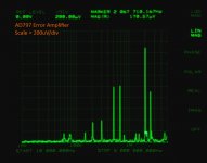
I've been comparing the super-regulators, actually about a dozen regulators of varying parentage. After wiring up another set of Walt Jung's design I put them on the HP3577a spectrum analyzer to see what's really going on. When you look at the results with a scope (a Tek 2465) there are no apparent issues whether the error amplifier is an AD797 or an AD825, but the spectrum analyzer tells a different tale.
The regulator output is connected to the spec analyzer via a pair of low leakage 10uF capacitors. (3577 gets unhappy with more than a 1.1 volts on the input.) I ran the analysis from 10kHz to 10MHz. It's not actually oscillating, the current would be a lot higher than what we're seeing. Le voila:
Attachments
Last edited:
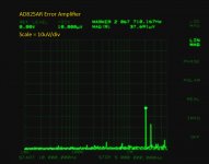
OK, you have me stumped. That's definitely NOT the kind of subtle difference I'd expect between two well-regarded, high performance opamps.. . . but the spectrum analyzer tells a different tale.
Those all appear to be discrete spectral lines - such as every AM radio station within 10 miles, and every microcontroller clock oscillator within 50 feet. And I'd probably start by looking for a grounding or shielding problem that found its way into the AD797 unit, but NOT the AD825 assembly. (I presume these are two separate units, rather than a case where something got disturbed in the process of changing out the opamps.)
Based on a cursory review of the Data Sheets at < http://www.analog.com/static/imported-files/data_sheets/AD797.pdf >, and < http://www.analog.com/static/imported-files/data_sheets/AD825.pdf >, the two chips seem to have roughly equivalent performance in the 0.5MHz to 5 MHz range, although the AD797 DOES have some finagling of the internal compensation in that area.
Any guesses as to what the underlying cause is?
Dale
Yes, the AD797 seems to do a better job of picking up the ambient noise -- the line ~700kHz is probably WABC which is a clear-channel station (although I don't think they run it up to 50kW). I'll take a peak tomorrow with the HP 3577 and the HP 3586, perhaps get a loop antenna going.
Yes, the AD797 seems to do a better job of picking up the ambient noise -- the line ~700kHz is probably WABC which is a clear-channel station (although I don't think they run it up to 50kW). I'll take a peak tomorrow with the HP 3577 and the HP 3586, perhaps get a loop antenna going.
I wonder if it is actually the chip picking up this stuff, or the circuit with it's wires and loops? Are this physically two different units?
jan didden
They are the same regulator PCB with the same connections -- uses the LM317 pre-regulator. Thus, you're just seeing the gain (and rectication) of the two device up through the a.m. broadcast band etc., etc.
I took care not to move the device on the device on the table top, nor any of the connecting wires. It is NOT in the box I've constructed to test the regulators.
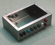
For the comparisons, I've built a bunch of these boxes to house the regulators. The regulator snaps into its power supply via a bunch of banana plug/jack. The DUT or measurement device snaps into the regulator on the other side, and it's provisioned for Kelvin connection of the error amplifier. I was going to use an umbilical, but it was easier and less expensive to drill holes. Regrettably, I couldn't find sufficient cookie tins this time of year.
I took care not to move the device on the device on the table top, nor any of the connecting wires. It is NOT in the box I've constructed to test the regulators.
For the comparisons, I've built a bunch of these boxes to house the regulators. The regulator snaps into its power supply via a bunch of banana plug/jack. The DUT or measurement device snaps into the regulator on the other side, and it's provisioned for Kelvin connection of the error amplifier. I was going to use an umbilical, but it was easier and less expensive to drill holes. Regrettably, I couldn't find sufficient cookie tins this time of year.
Attachments
I suggest a very simple check that could be helpful. With the spurious signals displayed, switch off the power to the reg, and see what changes.
All instances of oscillation I've seen with these regs have always been with tens if not hundreds of mV of sine wave output. I do agree with the observation that a time domain plot won't show this lower level stuff.
wj
All instances of oscillation I've seen with these regs have always been with tens if not hundreds of mV of sine wave output. I do agree with the observation that a time domain plot won't show this lower level stuff.
wj
- Status
- This old topic is closed. If you want to reopen this topic, contact a moderator using the "Report Post" button.
- Home
- Amplifiers
- Power Supplies
- Super Regulator, collecting the facts