Hi There,
Is it feasable to use an LM317 regulator on each side of a split transformer? The idea is to use two LM317s to get more amps available to an audio IC. Will this work?
(I'm normally into mechanical engineering type stuff, and relativly ignorant of electronics)
Thanx
The Happy Hippy
Is it feasable to use an LM317 regulator on each side of a split transformer? The idea is to use two LM317s to get more amps available to an audio IC. Will this work?
(I'm normally into mechanical engineering type stuff, and relativly ignorant of electronics)
Thanx
The Happy Hippy
How much current do you actually need? the official limit of an LM317 is 1.5A (depending on package), but as SY said see the app notes (or datasheet) to see common circuits for increasing the current capability, as I think this would be a much simpler (and probably less problematic) way to do it ")
Tony.
Tony.
Thanks guys
As to current, 1.5 amps is pushing it. I hope to get 56 watts out of an audio amplifier that is powered by this setup, and I'm planning on about 30 t0 35 volts, so I'd like to make sure that I have enough power. And that means, to me, that I need two LM317s. Also, I try to stay away from complicated thinmgs like transistors. The amplifier is based on a lm3876 chip, with caps and resistors in various places. I'm mainly shooting in the dark; my first priority is to avoid burning down the house.
Thanx
The Happy Hippy
PS. Does anyone have a schematic that shows exactly what resistors to use for getting 30 volts or 35 volts out of this Lm317? A pot or variable resistor does me no good in this situatiuon.
The application is a bit unclear to me. The LM317 will not provide more amps - the only way to do that is to increase the voltage or lower the resistance. I have doubts that the LM3876 requires a regulated supply, so a typical 3-pin regulator circuit would seem somewhat counterproductive.
Eureka!
OK! I just answered one of ny own questions. When all else fails, read the instructions. On the LM317 datasheet, it clearly states that you can use a LM137-337 series regulator to put on the negative side of the power supply. Is't that wonderful! However, I still don't know what resistors and cap to use for 35 volts. Any thoughts will be appreciated.
Thanx
The Happy Hippy
When all else fails, read the instructions.
When useing a Pass transistor there isn"t anything complicated about it , it is just a component like any other and probably less complicated to work with and take up less space than useing 2 regulators .......
If you look in the Datasheet there is a circuit in there useing a pass transistor that isn"t complicated and if you use the values shown you shouldn"t have any issues .....
If you look in the Datasheet there is a circuit in there useing a pass transistor that isn"t complicated and if you use the values shown you shouldn"t have any issues .....
The formula for output voltage is given on the datasheet- 1.25(1 + R2/R1). So if you choose R1 as 120R (this causes the regulator to put out ~10mA minimum, since output-to-sense is 1.25V), then you can solve for R2. Output voltage is 35V, so 35 = 1.25 (1 + R2/120), and then R2 = 120(35 - 1.25) = 4050 ohms. Nearest 1% values are 4020 and 4070, good enough.
Idea?
My idea was that, if I need more that 1.5 amps, then I can put one regulator, each good for 1.5 amps, on each side of a split power supply, and get the necessary amperage. I have been told, by my genius friends, that if I have 50 volts AC coming out of a transformer, it will knock down to 35 volts DC. (50 times the sine of 45 degrees, .7071) Also, voltage regulators are supposed to smooth out the flow of the electricity, I think. and getting 56 watts out of the amplifier, which is the purpose of all this, seems to mean that I'll need a little over 1.5 amps. And there maybe a voltage drop someplace, down to around 32v or even 30v. So, that's the basic idea. Will that work?
Thanx
The Happy Hippy
When all else fails, read the instructions.
Yes, that's more or less the idea. If you have higher voltage from the transformer than the chip amp can handle, some of it has to be dropped somehow. If you drop 15 volts across the regulator at 2 amps or more, it will need a substantial heatsink.
edit: As far as the voltage for the chip, National says, "Operation is guaranteed up to 84V, however, distortion may be introduced from SPiKe Protection Circuitry when operating above 70V if proper thermal considerations are not taken into account. Refer to the Thermal Considerations section for more information."
edit: As far as the voltage for the chip, National says, "Operation is guaranteed up to 84V, however, distortion may be introduced from SPiKe Protection Circuitry when operating above 70V if proper thermal considerations are not taken into account. Refer to the Thermal Considerations section for more information."
Last edited:
I think that your genius friends have been leading you up the garden path somewhat... they aren't evil genius' are they?
if you take the RMS voltage of the transformer (and they are always specified as RMS voltage) then you actually need to multiply that voltage by 1.414 to get the approx rectified DC voltage so a 50V transformer will actually have around 70V DC This will be way to much to then regulate down to 32V (but as already mentioned for a power amp, a regulated supply is not normally used).
As a rule of thumb, you can use the same AC voltage transformer, as the DC voltage you want after regulation, assuming you are just using a standard cap after the rectifier, and no resistors or inductors between caps.
Tony.
Apology
Looks like I didn't say that I was talking 35 volts per side, or 70 volts across. Sorry bout that. Anyway, now I'm thinking 30v or 32v, (60 or 64 across). The amp chip I'm using, LM3876, is good for up to 84v signal strength across, according to the data sheet. What I'm concerned with now is power coming in to the regulator. If a transformer puts out 48 volts, theoretically I get 33.94 volts DC after the rectifier. How much do I loose in real life? What happens if the voltage in gets below the set level? Or, how much over can the voltage in be before the regulator has problems? In other words, how close does the voltage into the regulator have to be to get the desired voltage out? And what happens if it varies? It shouldn't bother the amplifier to much, but how about the rest of the system?
Thanx
The Happy Hippy
Here's another cheat you can do- bypass some of the current around the 317. Suppose your load is 1 amp minimum, 1.5 amps normally, but can spike up to 2 amps at heavy drive. Then size a resistor (Ohm's Law) to pass 1 amp from the raw supply to the load, then use the regulator to supply the remaining 0.5-1 amp. That halves the dissipation of the regulator, and because of the voltage divider effect of the reg output, doesn't increase noise and ripple very much.
Example: Suppose your raw supply is 45V and the currents are as before. You want 35V regulated. For the 1A minimum current, the resistor bypassing the 317 would be R = (Vin -Vout)/I = (45 - 35)/1 = 10 ohms. Power would be 10W, so you'd probably want to use a 20-25 watt resistor. At normal loads, the regulator now only has to dissipate 5W.
Example: Suppose your raw supply is 45V and the currents are as before. You want 35V regulated. For the 1A minimum current, the resistor bypassing the 317 would be R = (Vin -Vout)/I = (45 - 35)/1 = 10 ohms. Power would be 10W, so you'd probably want to use a 20-25 watt resistor. At normal loads, the regulator now only has to dissipate 5W.
Genius vs. Nongenius
OK I seems that I made one tiny mistake. AC to DC - DIVIDE, not multiply, by .7071. (Or multiply by 1.414, which is the reciprocal of .7071). My genius friends were not clear on that point. Also, in some of the design work I am trying to do, I was confusing different types of rectifiers; half wave, full wave, permenant wave, big Hawaiian wave, etc. So, that actually makes it easier. I will need a 24 volt AC output transformer to get my 30+ volts. Thanks to all of you who very patiently explained this to me.
Thanx
The Happy Hippy
__________________________________
When all else fails, read the instructions
As to current, 1.5 amps is pushing it. I hope to get 56 watts out of an audio amplifier that is powered by this setup, and I'm planning on about 30 t0 35 volts, so I'd like to make sure that I have enough power. And that means, to me, that I need two LM317s. Also, I try to stay away from complicated thinmgs like transistors. The amplifier is based on a lm3876 chip, with caps and resistors in various places. I'm mainly shooting in the dark; my first priority is to avoid burning down the house.
Thanx
The Happy Hippy
PS. Does anyone have a schematic that shows exactly what resistors to use for getting 30 volts or 35 volts out of this Lm317? A pot or variable resistor does me no good in this situatiuon.
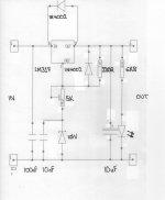
This is a circuit that I used to provide +36V but you do need to put a 1K resistor in series with the variable resistor.( Between the bottom of R2 and the Kathode of the zener)
At this voltage though, the LM317 is sailing very close its limits.
You would be better with a discrete component regulator if in fact you need one at all.
Attachments
- Status
- This old topic is closed. If you want to reopen this topic, contact a moderator using the "Report Post" button.
- Home
- Amplifiers
- Power Supplies
- LM317