Thanks to all that took the trouble to answer my little quizz at the end of my shunt reg column in the September Newsletter.
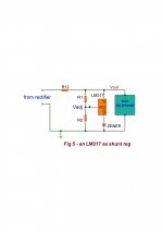
The question was: given a 6.8V zener in the attached circuit, size R1 & R2 for 15VCD output.
The insight needed was that the adj terminal of the 317 is always 1.25V below the output terminal. With the output terminal at 6.8V that puts the adj terminal at nominal 5.55V. So there will be 5.55V across R2 and 15-5.55= 9.45V across R1. According to ohms law, if we know the current through the resistors, we can calculate the R value, of course.
Actually we can just pick a current we fancy it seems, but there's two other considerations. There's a minute current coming out of the adjust terminal, flowing through R2 which may upset the correct voltages so we chose the current high enough that the adj current is insignificant.
The first answer I got was from Dick Middelkoop and he followed this exact reasoning, chosing 5mA current and getting R1 = 1.8k and R1 = 1.057 k, say 1k.
Fred Dieckmann came up with a very similar reasoning but 3 days later.
So, I nominate Dick for the Grand Prize, an F4 or F5 board set from the diyaudio store! Congrats!
jan
Attachments
Last edited:
Several other replies:
A VERY complete and accurate reply came from Jean Herdies from Brussels.
He actually calculate the values taking care of the adj current, so he needs much less current through the resistors. This would be a good solution for minimal power draw for instance in battery powered equipment.
His solution is a model of accurate work, see below.
Vo = 15V
Vz=6,8V
Vref= -1,25V
Iadj= 50µA (from specs)
Equations:
(I1+I2) . R2 = Vz+Vref= 6,8-1,25=5,55V (a)
(I1.R1)+((I1+I2).R2)=Vo=15V (b)
=> (Substituing (a) in (b)): I1.R1+5,55=15 => I1.R1=15-5.55=9,45V
=> I1 = 9,45/R1 (c)
=> substituing ( c) in (a) : (9,45/R1+50.10-6).R2=5,55 => R2 = 5,55/((9,45/R1+50.10-6)
R2 depends solely on R1's value
Let's assume
R1 = 10 kOhms
=> R2 = 5,55/(9,45/10000+50.10-6)= 5,55/0,000995=5577,889 Ohms
=> R2 ~ 6k2 // 56k (5582 Ohms)
Verification
=> substituing R2 and I2 in (a) : I1=(5,55/R2)-I2 => I1~944,27µA
=> substituing I1, I2, R1 and R2 in (b): Vo=(I1.R1)+((I1+I2).R2)~14,99268V
The real value depend on the precision of the components (Zener, Vref of the regulator, resistors)
Value of R12 depends on the current drawn by the load, the value of the input voltage, the admissible power of the Zener the admissible power of the 317 and the load regulation (those values were not provided).
Last edited:
Other solutions:
Kenneth: R1=1.7*R2 which is correct;
John also calculated the ratio of R1 and R2 correctly;
Koen mentioned correctly that the zener 'softens' the regulation and proposes to use a lower-impedance reference (but Koen, Vadj = 6.8-1.25 not 6.8+1.25);
Paul took the same route as Dick but selected 10mA standing current which leads to half the resistor values of course. That is the secong consideration I
mentioned: setting the current too high leads to needless dissipation. Personally I would go to 3 or 5mA although 10mA isn't wrong of course.
Omar also used a relatively large current:
"Let R12 = 125R, R1 = 4K7 is ok for our purpose here. As long as you are using a 6.8V zener here, the original LM317 calculation Vout = 1.25 x (1 + R2 / R1), Vadj will become 6.8-1.25 = 5.55V rather than 1.25V. Hence the formula becomes Vout = 5.55 x (1 + R2 / R1). R2 is 8K."
Sasmit took the opportunity to size the series R, R12:
"The resistor (R12) sizing would depend on the supply voltage and the current draw. Given a 6.8 v zener and a 15V output, we would need at least 21.8V at the input. Assuming a current draw of 1A and supply voltage of 25V the resistor would need to drop around 3 volts. 3 ohms * 1 A , I think a 2.7 ohms 5 W resistor would work."
Finally, Csaszar gave a correct solution but didn't explain how he got there.
Thanks again guys!
jan
Jan,
One issue about shunt regulators is that the bandwidth is better if you use a PNP on a positive rail as the shunt element. That way the final stage is a follower. (Follows for FETS, reverse polarity etc.)
ES
Yes. One member, 'nevermind' just reminded me that teh zener is the weak element. It's dynamic impedance decreses the regulation accuracy and increases Zout. In my own experiments I have tried a 5V LT4040 which has much lower dynamic impedance than a zener and the regulation is better.
jan
Yes. One member, 'nevermind' just reminded me that teh zener is the weak element. It's dynamic impedance decreses the regulation accuracy and increases Zout. In my own experiments I have tried a 5V LT4040 which has much lower dynamic impedance than a zener and the regulation is better.
jan
I don't know how often I mention that zeners around 6.2 - 6.8 volts work the best. Lowest dynamic Z and best tempco. Of course placing a capacitor directly across a zener is not particularly effective as it has such a low dynamic Z. An RC decoupling network is better but that requires a buffer. If the buffer is a simple transistor or two you lose the tempco advantage so you might want to go up to a slightly higher voltage zener.
For something complety different.
Why not put a 9 volt battery in series with the adjustment terminal. The very small adjustment current will act as trickle charge for the battery, and the battery adds practically no noise, and is free of dynamic impedance influence in this circuit location. You might have add some protection for power down conditions and I would suggest this would be best for an always on circuit which I belive all audio circuits should be except power amps. I think putting active voltage references between the out terminal of the LM317 and ground be looking for some real stability issues as well.
http://www.national.com/an/AN/AN-181.pdf
Better late than clever,
Fred Dieckmann
P.S. Doesn't that qualify for at least a T-shirt (Xtra large)
Hi Fred, nice to see you here again!
You bring up several good points. The battery stuff will surely work but I personally don't like to use them as they always seem to die on me at the pinnacle of a great demo ;-)
I don't agree that the impedance in the output leg, a zener or other ref, worsens stability. In my experience, the larger the dynamic impedance, the *better* the stability. Which is logical; it decreases the loop gain, so less stability issues (but also less good regulation).
Edit: No T-shirt I'm afraid; this is all for the honorary mentioning. ;-)
jan
I didn't even tried to participate , from 3 reasons :
1. you didn't provide BOM , and without BOM .... I'm - just as every proper DiyA - helpless .....
2.there is more fun fiddling with really poor LM337 ; you used slightly better cousin , so there is no fun .
3. I like it shiny ... so I'll return it with LED String instead of zener .....
4. I'm dumb ; and lazy ; fact . so - I'll return it with either R1 or R2 bypassed with small cap , depending which variant show less trouble on scope
P.S.
C'mon Fred,
you know very well that union rules require a (filmed) guarantee that the quiz is rigged before there's any talk about handouts.
(how's the other leg ?)
Yes a LED is a good solution. I don't know the Z of a LED but maybe it is lower than the 6.8V zener.
Typically 3-10 ohms.
Typically 3-10 ohms.
A 6.2 volt 1 Watt zener is typically 2 ohms but some go as high as 3!
Yes a LED is a good solution. I don't know the Z of a LED but maybe it is lower than the 6.8V zener.
.....
yeah ; they have much nicer noise/res figures but most important is that they're more shiny than zeners
")
......
About being lazy; that makes two of us ;-)
.....
naah ; you're exactly one degree and few magz less lazy than I am
.....
BTW Looking forward to see you at BAF!
jan
and vice versa ; just be sure to have in bag (still not bought) magz for Dutchiewhale and moi ........ I presume that I'll read all books going to SF , so I'll need something for going back .....
The battery can be replaced by a zener or voltage reference biased by a jfet current source from the regulated output voltage (Vin terminal of LM317). I am really wary of something "active" (like a LM329 for instance) between the LM 317 Vout and ground. Usually their output impedance is rising with frequency as is the LM317s Vout terminal impedance. Doing the DC level shifting outside path where signal current is changing just makes more sense as well; since you are trying to establish quiet, stable reference voltage for the feedback resistors to compare the output voltage against. One can make the obvious arguments against creeping compexity but three or 4 active components for a regulator isn't too bad.
I'll make due with my present T-shirt collection. Someone we know might punch me for wearing a DIYaudio shirt anyway.
I'll make due with my present T-shirt collection. Someone we know might punch me for wearing a DIYaudio shirt anyway.

Whoops.... Yes, level shifting external to the 317's Vout terminal will require biasing a voltage reference to from NEGATIVE VOLTAGE SOURCE and be of a value(Vreference minus 1.25 volts) to shift the Vadj voltage to a positive voltage since the R1/R2 voltage divider junction must sit at a positive votage between the regulator output voltage and ground.
The battery works because it can move Vadj below ground without an addition negative supply. Not the case with a zener, led string, or votage reference external to the 317's Vout terminal. All would require a negative voltage source and push to design to too much complexity. Mea Culpa, my mind was still in the battery reference mode ( which I still think might be the way to go...)
Good thing I didn't have to pay postage to return a T-shirt....

I will ask a stupid question:
Is this only a theoretical simulation or is this real world circuit?
If this is only an theoretical exercise, then everything is OK and fine.
If this is a practical circuit, then I would agree with Fred. Some time ago I tried Zener diode in series with shunt element (diode acting as level shifter) and got nothing but start problems and poor regulation.
- Status
- This old topic is closed. If you want to reopen this topic, contact a moderator using the "Report Post" button.
- Home
- Amplifiers
- Power Supplies
- Jan's quizz in the February Newsletter