I will ask a stupid question:
Is this only a theoretical simulation or is this real world circuit?
If this is only an theoretical exercise, then everything is OK and fine.
If this is a practical circuit, then I would agree with Fred. Some time ago I tried Zener diode in series with shunt element (diode acting as level shifter) and got nothing but start problems and poor regulation.
I have played with this circuit, and just as simulation (and common sense) predicted, the regulation gets worse with an impedance in the output leg, like the dynamic Z of a zener.
I didn't have any start-up problems though. Might depend on circuit particulars; can you post a circuit?
jan
One or two informations, for those unfamiliar with simulators.
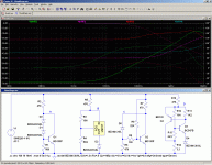
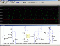
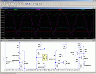
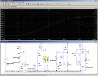
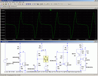
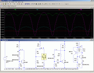
The behavior of the regulators is studied by looking at the transfer of 8Vpp ripple superimposed on the 20VDC power source, V1 (time domain).
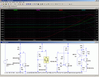
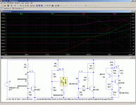
Frequency domain is identical, except the ripple frequency is swept from 10Hz to 10MHz, and is small signal.
The behavior of the regulators is studied by looking at the transfer of 8Vpp ripple superimposed on the 20VDC power source, V1 (time domain).
Frequency domain is identical, except the ripple frequency is swept from 10Hz to 10MHz, and is small signal.
The problem I have with for instance the green V(n003) is that in the freq domain it has the best suppression (-70-something dB) while in the time domain it has the highest ripple amplitude. I can't make any chocolate from that  . Unless I miss something grandiosely?
jan
jan
Last edited:
OOoops!!!The problem I have with for instance the green V(n003) is that in the freq domain it has the best suppression (-70-something dB) while in the time domain it has the highest ripple amplitude. I can't make any chocolate from that. Unless I miss something grandiosely?
jan


LTspice seems to have played tricks on me: the colors did change between the frequency and time domains.
Sorry for the blunder.
Here are the two diagrams side by side again, hopefully with consistent colors this time.
Two of the circuits are compensated. They should be easy to spot from the time domain.
I would think D is the red trace, and wonder how critical the various circuit values are wrt device variations.
On the C circuit, I wonder how it would look if R8 were filtered? Or do you need R8 to cancel partly the ripple?
For the B circuit, could you run that with an ideal voltage source instead of the zener in the 317 output leg?
Edit: red=C, green=C, magenta=B and pink=A I think.
jan
Last edited:
That is correct, and for a given output voltage, the sensitivity to components is low.I would think D is the red trace, and wonder how critical the various circuit values are wrt device variations.
The value of R14 must be adapted accordind to the voltage, but once it is done, components variations have little effect.
Filtering R8 would cancel its compensating effect.On the C circuit, I wonder how it would look if R8 were filtered? Or do you need R8 to cancel partly the ripple?
Here it is:For the B circuit, could you run that with an ideal voltage source instead of the zener in the 317 output leg?
Green=C is correct, so is magenta=B, but there is no pink trace?Edit: red=C, green=C, magenta=B and pink=A I think.
Attachments
Interesting! Looks like the zener is indeed the weak factor in (B). With a voltage source instead, it's almost as good as the best at least for lower frequencies.
BTW You can gain another handfull of dB's ripple supression by putting a cap across the top resistor of the output voltage divider.
jan
BTW You can gain another handfull of dB's ripple supression by putting a cap across the top resistor of the output voltage divider.
jan
Feb newsletter Quizz
Thanks for all who send in a reply to my little quizz in the Feb. newsletter:
To balance or not to balance, that's the question..."
The question was: with an unbalanced connection, if you tightly twist the signal and return wire, to minimize RF pickup by keeping loop area small, what might actually become worse?
In my opinion, that was the induction of noise and ripple flowing in the return (ground) wire into the signal wire.
But several people responded with different views which I believe makes at least as much sense.
Some pointed out that for audio frequencies the inductive coupling would be weak, but that the capacitive coupling of unwanted noise into the signal wire would become bad, and that's a good point.
Others thought that the inductance or capacitance of the connection would lead to attenuation of the high frequencies in the audio band.
In theory that is possible but I believe that the capacitance and inductance is too low to cause an audible roll off with reasonably low output Z preamps and high input Z poweramps.
Anyway, I hope that I made clear why, if you have a choice, balanced lines are better, even if only impedance balanced and not signal balanced.
Now to the prize (a pair of boards from the diyaudio store):
I numbered all entries that addressed the points above, and had an innocent hand (my wife) pick a number:
Member keantoken is the winner! Congratulations!
Let Mark (Variac) know what you want, and he will ship it to you.
Thanks again everybody for taking the trouble to think about this and mail me.
I'll try to come up with something interesting again for the next newsletter.
jan didden
Last edited by a moderator:
No, it will rather improve performances by lowering the screen cut-off frequency, and will help the assembly act as a balun, like the ferrites you clip on cables.Thanks for all who send in a reply to my little quizz in the Feb. newsletter:
To balance or not to balance, that's the question..."
The question was: with an unbalanced connection, if you tightly twist the signal and return wire, to minimize RF pickup by keeping loop area small, what might actually become worse?
In my opinion, that was the induction of noise and ripple flowing in the return (ground) wire into the signal wire.
It equalizes the levels of induction on the signal and return wires, cancelling the effects at the receiver side
No, it will rather improve performances by lowering the screen cut-off frequency, and will help the assembly act as a balun, like the ferrites you clip on cables.
It equalizes the levels of induction on the signal and return wires, cancelling the effects at the receiver side
Hi Elvee,
Just so I understand: are you talking about induction from external sources?
I was talking about induction from ground wire current into signal wire.
jan
On a balanced connection, noise induced equally into the signal and ground wires will not cancel out; the interference on the ground line will be ignored but the interference on the signal line will not. A ferrite on an unbalanced connection is a bad idea because it will increase the noise induced into the signal line by ground currents. It may help, if the noise from EMI was much greater than that induced by ground currents.
- Status
- This old topic is closed. If you want to reopen this topic, contact a moderator using the "Report Post" button.
- Home
- Amplifiers
- Power Supplies
- Jan's quizz in the February Newsletter
 :
: