Hi guys
I was not very active lately on the forum (being quite busy at work and home, moved from China back to France, and somehow changed lifestyle in the process...)
Andrew PMed me on the topic of the SSLV calculatot modifications requests and I promised I will give a look at it this weekend at the latest... traveling for work atm so its not convenient for me but ill do my best to react quickly
Cheers
Fred
Right said Fred! Long time to have seen you around indeed. Your calc contribution proved very popular all this time. Congrats! For when to update it, keep in mind also that the Leds won't give their 20mA Vf nominal value in this circuitry, better look in typical red and green LED datasheets for an average @3mA forward voltage drop value on their curves. Regards & happy new year!
The BOM would be individually diversified for transformer choice, R101/201 choice, and voltage trimmer value mainly.
In your situation I would get a 18+18V (two+two wire secondaries) 50VA transformer. I would have the four green CCS Leds all stuffed, start with 6.8R 5W R101 R201 (have 5.6R 5W R201 also because non matched IRF610 can present higher Vgs than IRF9610, you confirm CCS current by measuring voltage drop across the setting resistors and dividing by their value). I would also choose 1K R103/203 and 5K VR105/205. Good luck finishing it.
All four ? Sorry but when I´m not completely wrong but there are only 3 places where to solder the diodes, D102-104, or am I wrong?
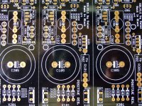
Check it again. Having a six months old board has to be able to use four Leds. Its revised like that a long time now just after the first batch. The guide mentions it also in its last paragraph: "In the newer batch of SSLV1.1 boards, 4 LED positions are available for ease in higher current settings. They can either be used for 3 LEDS and one of them be a wire jumper, or be fully populated if your current demands push VGS and your resistors stock fits higher values" It should be looking like the attachment.
Attachments
Ok will check tomorrow... Like I said, at the moment still in Saudi. Just done the BOM for my regulator, only not sure when it comes to C101/C102 and C103/C104...
Want to use it as PSU for the Twisted Pear Legato, and this seems to be a capacitive load. Which would U recommend then?
Want to use it as PSU for the Twisted Pear Legato, and this seems to be a capacitive load. Which would U recommend then?
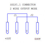
Hmm because described as low noise design maybe elcos only. Elna Silmic II 470uF/25V C101/202 & 47uF/25V C103/C203. Don't forget to jumper R107/207. Also two wire mode because I see a ground plane. The consumption nodes will not be defined. Two wire mode is done by soldering jumpers between +F +S and F0 S0 respectively under the output connector. Same for the negative -F -S board. Then you connect to your client board with 16-18 AWG short enough lengths from the far left & far right +/0 -/0 screws.
Hi have question
I use tran 36-0 the raw voltage is 48-49V and need 41.5 V for supply .
every thing is ok but I could not adjust the voltage more than 37.5 V
I chang R 201 from 13-50 ohm still cannot get more than 37.5
this set of tran I have use before in same condition and can get 41.5v
now I change the another board . and the other thing was difference is type of led could it cause for problem in this case.
Im thinking to change salasys diodes for ideal bridge controler like LT4320 http://cds.linear.com/docs/en/datasheet/4320fb.pdf No swithing like normal bridges and diodes. What do You think about it?
A thread on claimed superb big expensive rectifier diodes http://www.diyaudio.com/forums/pass-labs/284314-better-rectifier-sit-1-a.html
report its work correctly now I put more 1.2 k to R103Good luck and let us know
thanks Mr salas again
another one please
the other board I made for my friend Pre-amp have problems
1. raw voltage 48-50V sometime switch on its work normally v across R201 is 1.2 v I got 43.5 v problems is I could not reduce the output lower than 43.5 V when I reduce trimpot the Voltage is gone down to 8 V and FET 610 get hot . this case when V across R201 is 1.2v output 43.5v pre can play song but for 15-20 min its lost the voltage down to 8v pre was hum and 610 hot.
2. some time switch on the voltage still 43.5 V but v across R201 is vary 800-900-1000 mv in this case preamp distort and hum
what I have done is change fet 610 and 530 and 2sk117 gr(idss is 4.5-5 ma) the problems still same measure current at 47r is 2.6 ma , I reduce r103 to 4.7k it cannot work when switch on 8V output immediately
Any suggest please
Check Q203 204 205, a jfet and/or BC transistor probably burned. Probable because at higher voltage a BC is getting hotter especially if the sinks are small and create a furnace around it. If you find dead BC sink the replacement with small metal hat or ventilate the whole build better.
So got home, just got a look at the PCBs... And you´re right, I already have the version with 4 LEDs...
About the bridges between F-0 and S-0... This is normally something for remote sensing, and for regulation of dafing out voltage loss ?
In any case connection i.e. four wire remote sensing or two wire local sensing, the sense circuit must close loop with the force circuit for the regulator to track itself or remote nodes. Else its flapping in the breeze.
- Home
- Amplifiers
- Power Supplies
- SSLV1.1 builds & fairy tales