Hi. With the help of Salas, I was able to troubleshoot my own PCB of Salas SSLV1.1 reg. It is now working just fine.
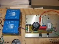
I didn't have access to the original 2SK117GR, and I do my own PCB. I did my own version of the SSLV1.1, with smd pads to use 2SK880GR. It is working great. Here my POS regs prototype on test.
I'll use it in my upcoming Soekris DAM1201 Dac.
Thanks again Salas
I didn't have access to the original 2SK117GR, and I do my own PCB. I did my own version of the SSLV1.1, with smd pads to use 2SK880GR. It is working great. Here my POS regs prototype on test.
I'll use it in my upcoming Soekris DAM1201 Dac.
Thanks again Salas
Attachments
Also listen with C101 & 201 470uF electrolytic instead of C102 & 202 plastic when it comes to digital. Depending on what subsystems it powers in there and if there is further local filtering or LDOs such a system can appreciate the lower 1/F noise with higher value chemical C101 or the faster film with C102.
Regulator for BA-3 FE: Maximum distance from load?
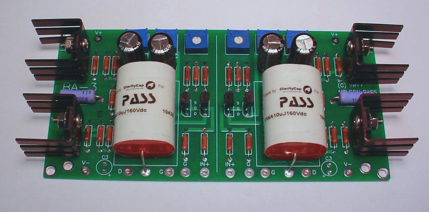
I am building a pair of Nelson Pass's BA-3 Front Ends (single-ended stereo configuration) to drive my two First Watt F4 power amps. Due to severe space limitations, each BA-3 will have to go into its own 288mm chassis
Galaxy 288 (3mm Front) - Compact with Quasi Heatsinks - Chassis There's no room to have both the BA-3 board
http://www.diyaudio.com/forums/images/articles/archive/fig7.jpg and your + & - regulator boards in the same chassis. So I thought about putting the toroid transformer and each pair of + & - regulator boards into another chassis, and then running umbilical cables from that chassis to each of the BA-3 board chassis. You say here http://diy.beyarn.com/bigdata/BIBguideRev2.pdf
“There are advantages of very low and relatively even and extended output impedance when using such a PSU…….This PCB works on remote sensing 4 wire ''Kelvin'' outputs. Remote sensing is good for disregarding the wiring resistance issue to correctly measuring the load demands by the regulator's error amplifier and effectively brings the load in touch with the regulator no matter the distance. Keeps the impedance low and gives you freedom of proximity to the circuits and arrangement. The wiring can be manageable gauge that way. Should be twisted pairs which you can twist yourself.”
So does this mean that I could run, say, a 3 to 4.5 foot cable between each regulator board and each BA-3 board without penalty?
Should the sense pair be a shielded twisted pair?I had done that and it works, but the sense pairs should be shielded coax because there is interference pick up danger.
A pair of coax using the cores as your sensing pair is no better than using two separated wires for the sense pair.
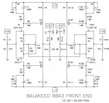
Are you familiar with the BA-3 Front End (not the complete preamp)? I know that Andrew and others at this thread are. Please see attached diagram.I had done that and it works, but the sense pairs should be shielded coax because there is interference pick up danger.
Nelson said that IDss should be between 6 and 12mA. Presumably, higher biasing would give better sound. I don't know very much; someone here agreed to do all of the calculations and building for me. Need two BA-3 boards; one each to drive each of my two First Watt F4 amps.
But at that IDss, is it better for a 100VA transformer's pair of secondaries to feed the rectifiers on a pair of reg boards-which, in turn, drive each BA-3 board? Or is one reg board enough to feed two BA-3 boards?
Attachments
Q3, Q4, Q103, Q104 will be the main consumers. (45mA per rail per phase). The front stage JFETs will just have to stay in IDSS given spec for resistors and trimmers drops to stay in adequate range for those MOSFETs bias control. If you want to avoid double mono regs then one positive and one negative can feed both channels. There will be somewhat less spacious quality VS double mono (i.e. VS four reg sections). They can run up to 1A CCS each. So their sourcing current ability is not a bottleneck.
With a balanced impedance ClassA push-pull circuit that maintains the balance through to the output, the current draw on each of the supply rails remains virtually constant.
To use this near constancy of current draw to best advantage, the +ve half of the PSU must supply both sides of the balanced circuit. The -ve half of the PSU must supply both sides of the balanced circuit.
It is easy to set up impedances and bias currents such that this driver stage never leaves ClassA and thus it becomes very easy to set up the PSU to supply the near constant current to the balanced circuit.
Do not split the PSU into 4 parts. One +ve and one -ve is best.
Read F5x for more background information.
Errr....I don't know how much difference this makes but I forgot to add that I am having my builder configure the BBA-3 as the single-ended BA-3 stereo front end. And we're building two of them to drive each of my two F4 amps for bi-amping my speakers. In this case, would one + & - pair of reg boards be fine to power both BA-3 boards, or would I still get much better sound quality by using two pairs?With a balanced impedance ClassA push-pull circuit that maintains the balance through to the output, the current draw on each of the supply rails remains virtually constant.
To use this near constancy of current draw to best advantage, the +ve half of the PSU must supply both sides of the balanced circuit. The -ve half of the PSU must supply both sides of the balanced circuit.
It is easy to set up impedances and bias currents such that this driver stage never leaves ClassA and thus it becomes very easy to set up the PSU to supply the near constant current to the balanced circuit.
Do not split the PSU into 4 parts. One +ve and one -ve is best. Read F5x for more background information.
If I lower the value of R101/201 to run slightly hotrodded will I need to reset the output voltages?
Thanks
Marra
That will only directly affect the current limit and dissipation. Maybe little different voltage drifts to dial out due to new temperature, i.e. nothing much to reset. Let it warm up first and check/trim Vout.
- Home
- Amplifiers
- Power Supplies
- SSLV1.1 builds & fairy tales