Correct. If silicone, its job is compensating the metal surfaces roughness enough after pressure is applied. In that case, grease would be only adding thermal resistance and smudge.
If hard like mica for high temp toughness, the grease will be filling the rough and its a plus.
If hard like mica for high temp toughness, the grease will be filling the rough and its a plus.
Correct. If silicone, its job is compensating the metal surfaces roughness enough after pressure is applied. In that case, grease would be only adding thermal resistance and smudge.
If hard like mica for high temp toughness, the grease will be filling the rough and its a plus.
My Si pads (as I showed in previously attached picture) are thin, soft and flexible. It is like a thin rubber flexibility type with about 0.5 mm thickness. So, I guess no thermal grease is needed.
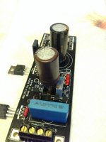
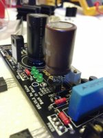
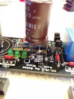
C301 and Elna 220uF 50V RFS Silmic, R301 and 8.2 Ohm Caddock MP-930
Hi Salas,
I finally got my BIB and I already assembled it (not tested yet).
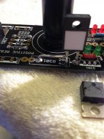
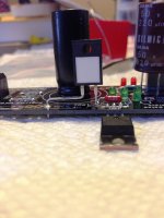
I have an issue to place C301 tightly. My Elna (220uF 50V RFS Silmic) is too big (16mm Diameter). I also hesitated with R301 (8.2 Ohm Caddock MP-930) placement. Please see attached pictures.
Can you also verify visually if all events are in correct places? It will give me a bravery to move forward and to test it with power.
I still need to assemble sinks and dummy load.
My dummy load is 930 Ohm 2 or 3W (I do not have 1k2 - (24V/20mA=1200 Ohm). Is it OK to use it?
Hi Salas,
I finally got my BIB and I already assembled it (not tested yet).
I have an issue to place C301 tightly. My Elna (220uF 50V RFS Silmic) is too big (16mm Diameter). I also hesitated with R301 (8.2 Ohm Caddock MP-930) placement. Please see attached pictures.
Can you also verify visually if all events are in correct places? It will give me a bravery to move forward and to test it with power.
I still need to assemble sinks and dummy load.
My dummy load is 930 Ohm 2 or 3W (I do not have 1k2 - (24V/20mA=1200 Ohm). Is it OK to use it?
Attachments
Visually OK. Small details can't be inspected in such a manner but it should be alright.
Dummy OK.
Hi Salas,
Could not get to the site for some reason.
Thank you and I'm going to test it today.
It is possible to replace both R305 and R303 with one resistor after final setup?
I can add R303 value (in my case I use Vishay 1k763 Ohm) to what ever value will be on Potentiometer for 24V output. So, I'll jumper R305 and I'll set R303 to new/constant value. What do you think?
If yes, then I will install single R303 with about 5K value and I'll be able to solder C301 correctly and tightly close to PCB.
Thank you.
Last edited:
The trimmer can be substituted to a fixed resistor after used for proper value hunting, no problem. Let it heat up and drift for half an hour in the final box with lid closed before readjusting for ref value.
The question is if I can substitute both (trimmer + R303) to one resistor after heat-up and drift adjustment. That one resistor will give me a space to push down C301 towards PCB.
Dummy guide for a Buffalo supply
Hey All
Im trying to use SSLV to build a PS for Buffalo.
Right now Im trying to figure out a BOM based on BJT mini kit.
According to the calculation in http://www.diyaudio.com/forums/power-supplies/192625-sslv1-1-builds-fairytales-169.html#post3107136 and other posts
I will need to buy additionally
4 diodes MUR820
R101 5.8R
R105 143R
R103 220R
C104 4.7uf/63v?
C105 10000uf voltage?
transformer 115v/9v 5va?
Anything else?
Hi Salas,
I tested BIB with dummy load and it seems working.
I kept it ON for 15 min and voltage dropped about 0.3V. So I adjusted it back to 24V exact.
I did not continue the test due to Q306 high temperature.
Q301 is also hot, but temperature there is less than Q306.
Dummy load is hot too and it is about at the same temperature as Q301 sink.
Q306 reached the point that I could not touch the sink with my finger for more them 5-7 sec.
Is it normal or I made mistake somewhere?
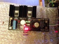
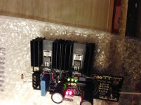
Maybe my Sinks are too small? Please see attached pics.
I tested BIB with dummy load and it seems working.
I kept it ON for 15 min and voltage dropped about 0.3V. So I adjusted it back to 24V exact.
I did not continue the test due to Q306 high temperature.
Q301 is also hot, but temperature there is less than Q306.
Dummy load is hot too and it is about at the same temperature as Q301 sink.
Q306 reached the point that I could not touch the sink with my finger for more them 5-7 sec.
Is it normal or I made mistake somewhere?
Maybe my Sinks are too small? Please see attached pics.
Attachments
What is the voltage drop across the Caddock? And what is its value in Ohm?
I just measured it = 1.601V. It's value 8R2.
195mA CCS and you spend 26mA, 4W on the output MOSFET, so the heat on such a small sink is to be expected. You will either utilize the chassis floor as sink if its substantial area, or you will use a chunkier sink.
I see. Let me try...
Thank you.
Hi Salas,
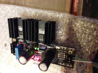
I use a big single sink now and it seems it is working fine. The temperature is lower and satiable.
I waited 30 min and adjusted BIB to 24V. Since then, there is no measurable drift (maybe 0.03V during 1 hour). However, it might be my Fluke internal fluctuations too.
Do I need to connect "0" to my "star GND"? Same star enclosure bolt when I connected Cu plane of my BHL MC & MM and TT GND lug. Thank you.
Nice and steady. Not bad for a "Norton" simple Vref used in this reg.
System grounding is a thing you must determine best by experiment. Each device & build is differently arranged. Start with just connecting the reg's output to the rail feed dedicated +V & 0V pcb points on your device. This keeps the DC cabling loop area narrow at least. If there is no extra hum & buzz introduced, better leave it at that. Else, experiment.
System grounding is a thing you must determine best by experiment. Each device & build is differently arranged. Start with just connecting the reg's output to the rail feed dedicated +V & 0V pcb points on your device. This keeps the DC cabling loop area narrow at least. If there is no extra hum & buzz introduced, better leave it at that. Else, experiment.
Nice and steady. Not bad for a "Norton" simple Vref used in this reg.
System grounding is a thing you must determine best by experiment. Each device & build is differently arranged. Start with just connecting the reg's output to the rail feed dedicated +V & 0V pcb points on your device. This keeps the DC cabling loop area narrow at least. If there is no extra hum & buzz introduced, better leave it at that. Else, experiment.
Thank you. I'll try it today and let you know.
Dummy guide for a Buffalo supply
Hey All
Im trying to use SSLV to build a PS for Buffalo.
Right now Im trying to figure out a BOM based on BJT mini kit.
According to the calculation in http://www.diyaudio.com/forums/power-supplies/192625-sslv1-1-builds-fairytales-169.html#post3107136 and other posts
I will need to buy additionally
4 diodes MUR820
R101 5.8R
R105 143R
R103 220R
C104 4.7uf/63v?
C105 10000uf voltage?
transformer 115v/9v 5va?
Anything else?
Hi
I am not using such a DAC but if you look at early posts here there have been some examples and discussions about the consumptions and the values by some members.
- Home
- Amplifiers
- Power Supplies
- SSLV1.1 builds & fairy tales