Hi folks. I have been working on a layout for a microphone preamp with 4-6 channels and switchable phantom power for each. I'm not completely sure yet of the preamp design. It will be balanced in, non-balanced out. Perhaps I would do an ina217 configuration or maybe OPA2134/2228 type opamp with differential on one side and inverted on the other side. Regardless, I am starting to think about the power supply for this and have a few basic questions. I'd like to stress that I want this to be very low noise floor.
I would need power for 48V phantom for each channel plus amp power for each channel. Most preamp designs I've seen on the web pull ~20mA, as does the opa2134 based amp I am testing now. The image below is my quick quick interpretation many designs I've seen on the web, using LM317T/337T for a +/-15vdc supply. Given the current draw of a preamp, am I correct in thinking I would have no problem running 6 channels off of this? Would powering 6 channels have any noise issues, how would I maximize the circuit to handle 6 channels, etc. Also, is this circuit correct, how could it be improved to minimize noise. I would be using a single, dual secondary Antec torroidal transformer, 0-15, 015, is 100VA enough, to much?
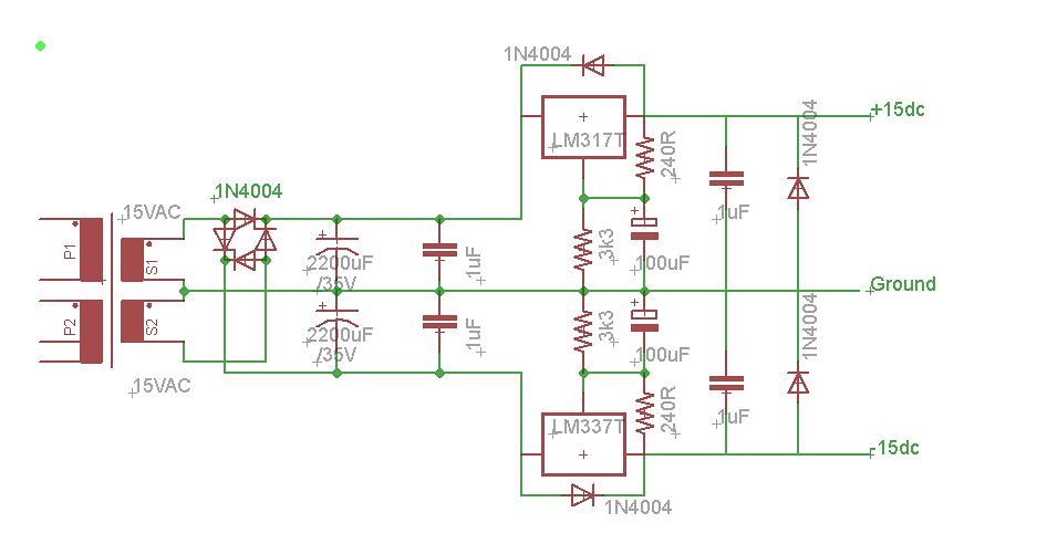
micprePSU by Dennis Dietz, on Flickr
Now for phantom power. It seems as though phantom is often taken right of of one secondary of the power supply transformer. Would this tend to lead to issues with a greater draw on one winding than the other. Would this lead to unwanted noise?
Last, would it be OK to use a basic LM317T circuit to boost the dc from the transformer (15*1.41-1.4=20vdc) to 48volts, as Minion linked in post #7 here, http://www.diyaudio.com/forums/parts/133032-diy-mic-preamp-48v-phantom-power.html? Again, noise issues, heat issues, etc I should worry about.
I would need power for 48V phantom for each channel plus amp power for each channel. Most preamp designs I've seen on the web pull ~20mA, as does the opa2134 based amp I am testing now. The image below is my quick quick interpretation many designs I've seen on the web, using LM317T/337T for a +/-15vdc supply. Given the current draw of a preamp, am I correct in thinking I would have no problem running 6 channels off of this? Would powering 6 channels have any noise issues, how would I maximize the circuit to handle 6 channels, etc. Also, is this circuit correct, how could it be improved to minimize noise. I would be using a single, dual secondary Antec torroidal transformer, 0-15, 015, is 100VA enough, to much?
micprePSU by Dennis Dietz, on Flickr
Now for phantom power. It seems as though phantom is often taken right of of one secondary of the power supply transformer. Would this tend to lead to issues with a greater draw on one winding than the other. Would this lead to unwanted noise?
Last, would it be OK to use a basic LM317T circuit to boost the dc from the transformer (15*1.41-1.4=20vdc) to 48volts, as Minion linked in post #7 here, http://www.diyaudio.com/forums/parts/133032-diy-mic-preamp-48v-phantom-power.html? Again, noise issues, heat issues, etc I should worry about.
What I used for Phantom power in my pre"s isn"t what I posted in that post you referanced but it is Simular ......
What I do is use a Voltage tripler right after the Secondary of the Transformer , when useing a 15v, 0v , 15v transformer I use one of the 15v AC taps and triple it to about 60v DC then regulate it to 48v with a 317.... as long as the transformer is able to handle the current draw there shouldnt be a problem with one side of the Transformer drawing more than the other pluss thats what regulators are for .......
What I do is use a Voltage tripler right after the Secondary of the Transformer , when useing a 15v, 0v , 15v transformer I use one of the 15v AC taps and triple it to about 60v DC then regulate it to 48v with a 317.... as long as the transformer is able to handle the current draw there shouldnt be a problem with one side of the Transformer drawing more than the other pluss thats what regulators are for .......
Fixed the diode direction and added a phantom part.
Do I need caps parallel on the bridge diodes?
What is a good value for the phantom large el cap?
Do all other cap values seem OK?
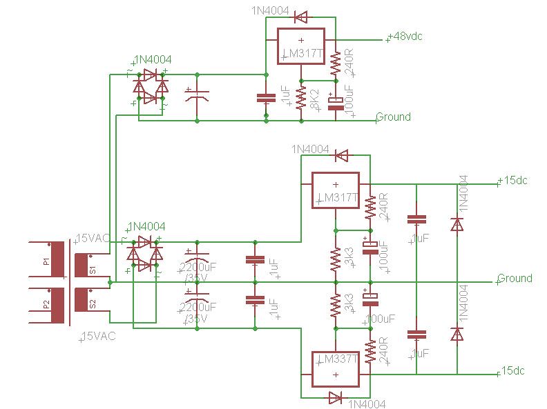
micprePSu2 by Dennis Dietz, on Flickr
Do I need caps parallel on the bridge diodes?
What is a good value for the phantom large el cap?
Do all other cap values seem OK?
micprePSu2 by Dennis Dietz, on Flickr
Last edited:
Thanks Minion,
Thant makes more sense to me considering I could not figure out how you could end with higher voltage than went in. I'd seen the voltage tripler with diodes on the green mic pre site (DIY Factory - green mic-pre) but had forgotten about that part. I really don't understand how that works though and would love an explanation.
Better???
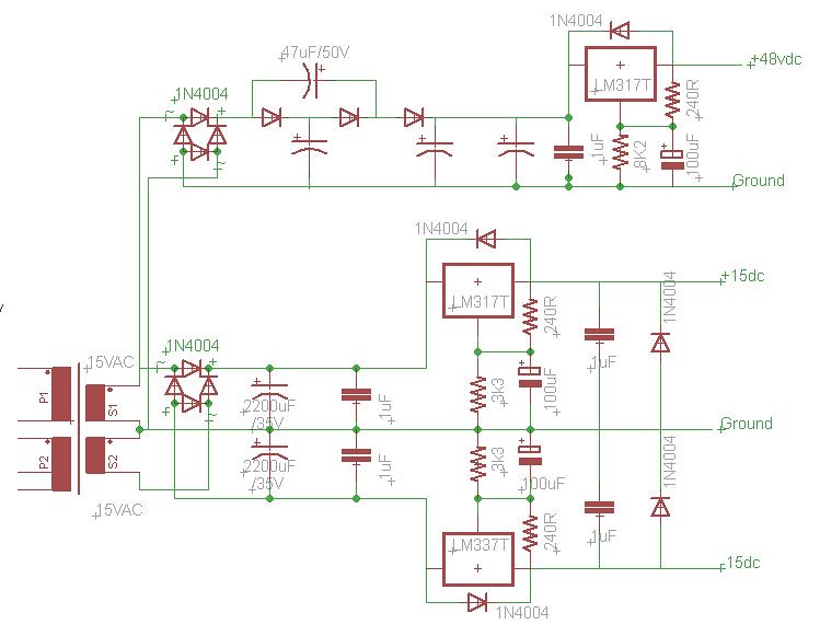
micprePSU3 by Dennis Dietz, on Flickr
Thant makes more sense to me considering I could not figure out how you could end with higher voltage than went in. I'd seen the voltage tripler with diodes on the green mic pre site (DIY Factory - green mic-pre) but had forgotten about that part. I really don't understand how that works though and would love an explanation.
Better???
micprePSU3 by Dennis Dietz, on Flickr
Er, and yes, I do realize I have the diodes at the bridge going the wrong way")
If you're using plain old power diodes you may want to add a 1000pF cap in parallel with each diode. Certainly design in the components as you may want them. It got the noise down on my 1982 preamp which I still use.
Have you looked into the mic preamps from THAT corp (THAT 1510/1512), Analog Devices SSM2019 or TI (Burr-Brown) INA217 ?
G²
I found a good, basic explanation of diode rectification and voltage multiplication here:
Voltage multipliers : DIODES AND RECTIFIERS
G^2, thanks for the advice. Inhad read it elsewhere and planned to add the ability for those caps when I layout an actual board. Would ceramic be suitable?
As for the dedicated chip, I'm not really opposed to them. I see them recommended frequently but rarely see anyone actually use them. Unfortunately, I've never heard any of the various options so I have nothing to work from. I'm not opposed to building a few different styles, but I want/need each to be useable and low noise from the beginning. I don't/can't waste the money building a channel that turns out bad sounding. That's why I've moved onto the powersupply for now. No matter that amp circuit(s) I use, they all will need a good powersupply of +/-12-18vdc and phantom power.
That reminds me.... I feel like I'm right but want to check. If I have 6 preamps (20mA idle and say 50mA load) plus 6 phantom lines (Rod Elliot suggests mics will only draw about 20mA each for 120mA total), that totals about 420mA. What then is a reasonable Amp rating for my transformer?
What I do is use a Voltage tripler right after the Secondary of the Transformer , when useing a 15v, 0v , 15v transformer I use one of the 15v AC taps and triple it to about 60v DC then regulate it to 48v with a 317.... as long as the transformer is able to handle the current draw there shouldnt be a problem with one side of the Transformer drawing more than the other pluss thats what regulators are for .......
How does the 317 handle that, I thought it had a 40V max voltage input?
Ahh, yeah, I totally read that wrong. Thanks!
Any thoughts on a RC filter for the PSU and my capacitor values for the PSU part?
Thanks!
I really don"t use RC filters , if you have enough capacitance I don"t think you really need the resistor .....
I do use CRC and CLC Filters in PSU"s for tubes amps because Capacitance is expensive at 450V but otherwize Ive never used them .....
Cheers
Ahh, yeah, I totally read that wrong. Thanks!
Any thoughts on a RC filter for the PSU and my capacitor values for the PSU part?
Thanks!
Be careful- on startup, you could easily exceed the max voltage rating.
The best ways to make a quiet 317 supply are to use a really large cap across the voltage setting resistor, a really large cap at the output, and a dummy load resistor to draw some significant (>100mA) current. Don't forget protection diodes.
So what are we talking here for cap sizes? First cap after rectifier at 1000uF, 2200uF, ...? Is 1uf enough for the nonpolar caps?
Sy, for a dummy load resistor, do you mean after the rectifier or after the regulator, I've seen resistors designed inline after the first large polar electrolytic, parallel after it, and parallel to an electrolytic output cap?
Thanks!
Sy, for a dummy load resistor, do you mean after the rectifier or after the regulator, I've seen resistors designed inline after the first large polar electrolytic, parallel after it, and parallel to an electrolytic output cap?
Thanks!
After the regulator. You want the reg to be supplying lots of current at all times- 100mA is a good target minimum. The cap bypassing the current setting resistor should be 1000+uF. Output cap can be that big, but 100u is probably enough- use an aluminum electrolytic.
These two measures will greatly enhance the regulator performance (output impedance and noise)- see "Understanding and Reducing Noise on 3 Terminal Voltage Regulators" by Erroll Dietz.
These two measures will greatly enhance the regulator performance (output impedance and noise)- see "Understanding and Reducing Noise on 3 Terminal Voltage Regulators" by Erroll Dietz.
After the regulator. You want the reg to be supplying lots of current at all times- 100mA is a good target minimum. The cap bypassing the current setting resistor should be 1000+uF. Output cap can be that big, but 100u is probably enough- use an aluminum electrolytic.
These two measures will greatly enhance the regulator performance (output impedance and noise)- see "Understanding and Reducing Noise on 3 Terminal Voltage Regulators" by Erroll Dietz.
Thank you Sy. I'll look up the reference you mentioned. In the meantime, your suggesting that after the 317 circuit placing from positive(or negative) to ground a +1000uF electrolytic, resistor to set current at 100mA, a 1uf nonpolar, and finally a 100uf or bigger electrolytic. I can then go right off of that to each chip power pin/board ground, bypassing the power right at the pin with a 100nf ceramic or 10uF electrolytic. Does that sound correct?
Thanks!
How does this look?
The Dietz appendix Sy referenced above seems to suggest 1.0uF or greater nonpolar at the adjust pin and low ESR greater than 50uF in series with the output. I never see schematics posted with a series output resistor and the values just mentioned are always smaller than I see in online schematics.
Thanks!
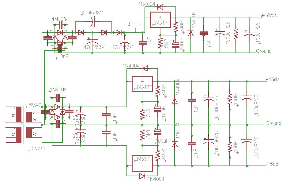
micprePSU4 by Dennis Dietz, on Flickr
The Dietz appendix Sy referenced above seems to suggest 1.0uF or greater nonpolar at the adjust pin and low ESR greater than 50uF in series with the output. I never see schematics posted with a series output resistor and the values just mentioned are always smaller than I see in online schematics.
Thanks!
micprePSU4 by Dennis Dietz, on Flickr
Getting there. A few things:
1. You need to ensure that the 48V reg doesn't fail on startup. There's a few ways to do that, depending on how much voltage you have to burn.
2. Get the bypass caps on the adjustment resistors larger- 1000u isn't too big and at those voltages, still pretty cheap.
3. You may or may not want those 1u bypasses.
4. You still need to diode-protect the ADJ pin
5. Make sure that the regs are heatsinked and the 150R resistors are sized to at least 0.5-1.0W.
Thanks you Sy.
1) Tell me more please. The voltage at the phantom 317 in pin is ~60v.
2). Ok. I've generally seen these as 10uf tantalum or up to 100uf el. Why so big?
3). Why. To be honest I thought they where there to help block high frequency ringing that is not heard but that migt cause distortion. I guess if there is space on the board I can just not put them in.
4)of course. That is obvious to me now. Thanks for catching that!
5). Yup, got that already. Though using p=iv, at. 100mA I'd need almost 2W right, especially since I might have 6 channels off this supply.
1. One easy method is to stick a 30V (or so) Zener across the chip.
2. See the noise and output Z graphs in the Dietz article. For whatever reason, audiophiles seem to want "fast" supplies- really, what you want is a slow supply, slow for the voltage to decrease with load steps, and no spikes or transients in the response. Smooth is the key. The big cap prevents fast response and more effectively shunts noise to ground.
2. See the noise and output Z graphs in the Dietz article. For whatever reason, audiophiles seem to want "fast" supplies- really, what you want is a slow supply, slow for the voltage to decrease with load steps, and no spikes or transients in the response. Smooth is the key. The big cap prevents fast response and more effectively shunts noise to ground.
- Status
- This old topic is closed. If you want to reopen this topic, contact a moderator using the "Report Post" button.
- Home
- Amplifiers
- Power Supplies
- Mic pre and phantom power PSU questions