Thanks again for the reply.
1). You mean from the in to the out pin? What does that do (I'm not very familiar with how a Zener functions), shunt the initial voltage around the regulator???
2). I'll try and look at those and better understand it. Obviously, I'm a very big neophyte here so the more theoretical or technical an explanation gets, the harder it is for me. Still, I can understand things when they are explained, I just don't have much background for trying to decipher things on my own. The web is a wondeful host of information, but eventually one can find every conflicting answer to any question")
1). You mean from the in to the out pin? What does that do (I'm not very familiar with how a Zener functions), shunt the initial voltage around the regulator???
2). I'll try and look at those and better understand it. Obviously, I'm a very big neophyte here so the more theoretical or technical an explanation gets, the harder it is for me. Still, I can understand things when they are explained, I just don't have much background for trying to decipher things on my own. The web is a wondeful host of information, but eventually one can find every conflicting answer to any question
You want it from out to in, yes. Cathode end (usually with the band) at the input. Under normal operation, it does nothing. At startup, it limits the voltage across the 317- basically, a Zener doesn't conduct (much) in reverse bias up to the Zener voltage, at which point it acts (mostly) like a short. When the voltage drops below the Zever voltage, it acts like a reverse biased diode (basically, an open circuit) again.
Thanks for the explanation. Let's see if I have this.
If the source voltage is greater than the Zener rating, current can flow through the Zener. In this case it acts like a short, allowing the current to bypass the 317 through the Zener. This could happen if there is a voltage spike, specifically here we are referring to at initial start up. Once th voltage falls to it's correct level, lower than the zener's breakdown voltage, it prevents the flow of current, which now must go through the 317.
I'd assume there is a threshold value here? By that I mean you want you Zener value to be some percent or something over the normal operating voltage, but lower then some percent than the max voltage for whatever it is protecting.
In this case, your recommendation of ~30V is for the regular power supply since the phantom is ~60V before the 317. Is that correct?
Thanks!
It's not the current surge- the chip is well-protected against that- it's the start-up voltage. Think of it this way- before power-up, the output caps (whatever they are) are at zero volts. We turn on the power. Until current starts charging the caps, the voltage between in and out is 60V. ZAP.
Now, we put a Zener clamp in. Turn on power, the Zener conducts, limiting the voltage across the chip to 30V. Now, the current flows into the caps through the Zener until input to output differential drops to 30V at which point the Zener turns off and further charging happens through the chip.
Use at least a 5W unit- 10W would be even better (you want the Zener to survive the turn on surge current). A 1N5363 should work fine and will cost less than 50 cents.
Awesome, that makes perfect sense. In my schematic, the protection diode 1N400x coil simply be replaced with the Zener you recommended, right?
Do I need this also for the +/-15 volt rails? I would not think so since the max voltage difference is never above 25V, but it never hurts to ask.
Do I need this also for the +/-15 volt rails? I would not think so since the max voltage difference is never above 25V, but it never hurts to ask.
Thanks for all the help Sy, Minion, and everyone else who has posted. I've learned quite a bit so far.
My last question seems regard the values for each capacitor. I realize I've asked this already but I'm finding it hard to determine good values. It seems as though the bigger one goes the better, but at some point size and cost out-weight the benefits. The Dietz article suggests not using low ESR, greater than 50uF parallel at the output and greater than 1uF at the adjust pin to ground. But, that is way smaller than what I see used or suggested.
My last question seems regard the values for each capacitor. I realize I've asked this already but I'm finding it hard to determine good values. It seems as though the bigger one goes the better, but at some point size and cost out-weight the benefits. The Dietz article suggests not using low ESR, greater than 50uF parallel at the output and greater than 1uF at the adjust pin to ground. But, that is way smaller than what I see used or suggested.
Figures C2 and C4 should give you a clue. As the output cap gets bigger, the noise peak gets smaller and pushed lower in frequency. Both are good- lower noise is a nice thing, and lower power supply noise frequencies are rejected more efficiently by most amplifier circuits. Greater capacitance on the adjust pin lowers the output impedance, especially at low frequencies. See the bottom two curves especially, where Dietz combined large caps with high currents.
Thanks Sy, I'll look at that more closely. I am a bit confused still but I'll try to figure it out.
Another question as I know start to lay out a board, I'm confused how to properly pull from one transformer secondary for the phantom section while dealing with the ground. I'm planning to connect the AC1 ground and AC2 hot leads to form a center tap. That becomes ground for the dual polarity supply, so connecting just AC1 secondary to a rectifier circuit connects that dual supply ground also but creates a new ground. Maybe my image below will clarify what I mean. Sorry the caps around the diodes makes it messy.
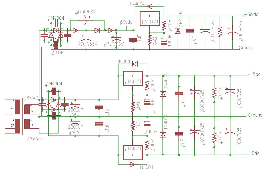
micprePSU4 by Dennis Dietz, on Flickr
Another question as I know start to lay out a board, I'm confused how to properly pull from one transformer secondary for the phantom section while dealing with the ground. I'm planning to connect the AC1 ground and AC2 hot leads to form a center tap. That becomes ground for the dual polarity supply, so connecting just AC1 secondary to a rectifier circuit connects that dual supply ground also but creates a new ground. Maybe my image below will clarify what I mean. Sorry the caps around the diodes makes it messy.
micprePSU4 by Dennis Dietz, on Flickr
It won"t work if you put a Diode bridge before the Voltage tripler , the Voltage tripler will rectify the AC to DC so no Bridge is needed.......
You also didn"t do the Voltage tripler properly .....
look here under "Voltage Tripler and beyond:
Voltage Multipliers
I used 100uF caps in the Tripler and a 470uf after the tripler ......
You also didn"t do the Voltage tripler properly .....
look here under "Voltage Tripler and beyond:
Voltage Multipliers
I used 100uF caps in the Tripler and a 470uf after the tripler ......
Thank you Minion. Looking over all that now I see now. Thanks for checking me. I know you've mentioned before loosely copying the Green Pre psu. Any idea why they took it up to 100V before the regulator they used? You only used three diodes and three caps in the triplet circuit, followed by a filter cap, etc?
Is there some sort of formula you used to arrive at your capacitor values?
Sy, thanks for the suggestion. I've though of that but I figured since any transformer I use will have plenty of capacity for both functions, and it means less parts in my enclosure and less RF from a second transformer. At least that is my thinking. I also have a couple 16vac smps wallwarts that seem to work fine with my breadboarded psu.
Hi , The Power supply i used was for a different version of the Green pre , probably a Later version , there were many versions that are posted over at Prodigy Pro... the version I used didn"t have the Voltage Quadrupler that is on the schematic that is on the Green pre site , it was just a tripler and a LM317 regulator ......
Sy, I see. So your suggesting to use a higher voltage transformer and simply rectify and filter? Wouldn't I need about the same number of parts? I guess I don't follow you. Thanks for setting me right about RF, I though it could be difficult to avoid hum or some kind of interference with more transformers.
Minion, thanks for clarifying that. I assumed as much but obviously I'm new at all this
Minion, thanks for clarifying that. I assumed as much but obviously I'm new at all this
I really don"t use RC filters , if you have enough capacitance I don"t think you really need the resistor .....
I do use CRC and CLC Filters in PSU"s for tubes amps because Capacitance is expensive at 450V but otherwize Ive never used them .....
Cheers
How big is big enough?
I've been testing various configurations and found that 1000uF alone (post rectifier) was not enough to eliminate 100Hz ripple on the output of the reg. 1000uF 3r3 1000uF pretty much eliminated it. I haven't posted those results yet in my LM317 experiments and measurements thread but will do so. I can't remember if I tried a single 10,000uF cap after the rectifier or not.
Also the size of the adj pin bypass cap can be significantly reduced using Fred Dieckmann's mod as demonstrated by my tests
in my case increasing it above 4.7uF seems to have minimal effect, I didn't try a large electro though, perhaps I can add that to the tests...Tony.
Transformers don't radiate RF, and it's pretty easy to avoid hum. Parts count will be reduced if you don't have to have a fancy tripler.
You are being a pedant SY
They can (and do) however radiate EMI (and it isn't necessarily just 50Hz hum) which may be picked up by sensitive circuits. Plenty of experience with that one I'm afraid
However a good transformer with appropriate placement should minimize the risk of that. Tony.
Tony, thanks do stopping by. I'll have to check out your other thread and I'm keen to see your results and solutions.
I don't mind using parts or having the tinyist board possible. As I have no way at thus time to see ripple, spikes, noise, etc in the output, I feel my best bet is to try and make sure it's not there in the first place. Obviously, that means copying the successes of others I really appreciate minion, Sy, Tony and others who are helping me learn here.
For what it's worth, I just put the diode voltage triplet on a breadboard amd can say I think I get it now. Thanks Minion for steering me right with that.
TI is sent my free samples today (Ina217, opa137, lm337 and a few others) so I'm keen to order the rest of my parts and get started.
I don't mind using parts or having the tinyist board possible. As I have no way at thus time to see ripple, spikes, noise, etc in the output, I feel my best bet is to try and make sure it's not there in the first place. Obviously, that means copying the successes of others
I really appreciate minion, Sy, Tony and others who are helping me learn here. For what it's worth, I just put the diode voltage triplet on a breadboard amd can say I think I get it now. Thanks Minion for steering me right with that.
TI is sent my free samples today (Ina217, opa137, lm337 and a few others) so I'm keen to order the rest of my parts and get started.
Well, a small 48V transformer, a bridge, a filter cap, and you're done. Given that the phantom power will draw no current, a couple of RC filters following the regulator will clean things up beautifully.
The key will be layout and grounding. Keep the transformer(s) away from the circuit, use types that have a shield between windings, and single-point grounding schemes. For my ribbon mike preamp, the raw power supply is in a separate box.
The key will be layout and grounding. Keep the transformer(s) away from the circuit, use types that have a shield between windings, and single-point grounding schemes. For my ribbon mike preamp, the raw power supply is in a separate box.
- Status
- This old topic is closed. If you want to reopen this topic, contact a moderator using the "Report Post" button.
- Home
- Amplifiers
- Power Supplies
- Mic pre and phantom power PSU questions