I found 390pf caused the transformer to vibrate a little.
With 1000pf it is dead quiet.
I obviously recalculated Rmin and Rmax to suit from the spread sheet.
Dont change the timing capacitor. Do the scope measurements I said and post the scope pictures if you can.
From the picture i can tell you if your dead-time is too small or too big.
So we can fine-tune your network
Dont change the timing capacitor. Do the scope measurements I said and post the scope pictures if you can.
From the picture i can tell you if your dead-time is too small or too big.
So we can fine-tune your network
I cant scope the primary as I don't haver an isolation transformer.
I can look at the secondary ok ?
1 uS per division.
An externally hosted image should be here but it was not working when we last tested it.
Last edited:
I cant scope the primary as I don't haver an isolation transformer.
I can look at the secondary ok ?
From the secondary waveform I cannot tell whether the dead-time is ok.

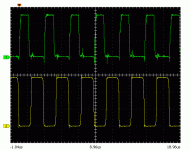
Here you can see my waveforms. Green is the low side FET gate, and yellow is the half bridge output.
The gate turns on (gets over 3V) just after the half bridge has sunk to low.
When the half bridge is sunk to low, you can see a negative spike. This negative spike is just before rising.
If this is negative spike is >100ns before the gate signal starts to rise, then you have too much dead-time.
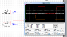
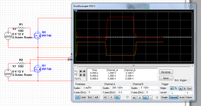
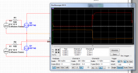
I did some simulations for you too (with IRF740, 200kHz switchin, 200uH primary inductance and 47nF resonant capacitor):

Here you can see a situation where dead-time is too much (it is set to 500ns). You can see that the negatíve spike happens about 400ns before the rise of the gate.

Here you can see a situation with proper dead-time (it is set to 100ns). The negative spike is just before the gate signal rise (like me scope measurements).
See that the half bridge slope is the same with big dead-time.

Here the dead time is set to very little (50ns). You can see a miller plateu-caused positive spike in the gate rising. Also note that the half bridge slop starts with a slow slope, then it changes at a ceratin point and sinks rapidly (hard swithcing, high dU/dt).
In the simulations a dead-time values of 200-100ns was found good for this situation. Usually there is no perfect dead-time value.
At no load swithcing freq is at maximum, so you must set the minimum needed dead-time. At load the switching fequency decreases and the magnetizing current gets bigger, also the leakage inductance helps you a bit, so FETs Coss charges more rapidly. At lower switching freq, a lower dead time is also enough.
Some ICs have adaptive dead-time (they change the dead-time with switching frequency).
But IRS27951 has a selectable fixed dead-time. So you must set it at no-load to the minimum needed value. It will be a bit much at high load, but no problem.
I have Fmin as 27,777Hz.
I Fr1 as 66,666Hz
I have Fmax as 133,332Hz
If I run my 27951 off low volts I get 43KHz as the minimum frequency.
I get 153KHz as the maximum frequency.
Is the 43KHZ close enough to 27,777Hz ? Should it not need to be close to the lower resonant frequency as possible but not below it ?
I Fr1 as 66,666Hz
I have Fmax as 133,332Hz
If I run my 27951 off low volts I get 43KHz as the minimum frequency.
I get 153KHz as the maximum frequency.
Is the 43KHZ close enough to 27,777Hz ? Should it not need to be close to the lower resonant frequency as possible but not below it ?
From the secondary waveform I cannot tell whether the dead-time is ok.
.
The highest isolated voltage I could find was 90 volts and this is what I get:
The first top upmost is the half bridge out and the other signal is LO.
Its looks around 800nS dead-time.
An externally hosted image should be here but it was not working when we last tested it.
I worked through the app notes again tonight.
Together with the spread sheet I tried to work out where everything was coming from.
I was getting the minimum switching frequency mixed up with the lower resonant frequency.
I also did a silly with the formulae, I used 10e-3 instead 10 power of -3 so was out by a factor of 10.
I now get the same values as the spread sheet for the control components.
Last edited:
The highest isolated voltage I could find was 90 volts
A nice tip:
If you don't have a transformer with higher voltage output, use a voltage multiplier rectifier to make the voltage higher.
You need to check the waveform at no load, so it only need to take few watts.
The circuit can be supplied with both 230VAC and 320V DC (then the rectifier brdige does nothing, but no problem
Q: how do you design the transformer with the aim of a certain Lleak? . Lm is no.problem (turns, core data, air gap) but how to make sure that you end up at the right ballpark?
spilt bobbin etc .
The reason is that I was at first considering using an external inductor but then I realised that it will have quite some current swing at high frequency, sinusodial (does not matter) . This rules out a cheap nifty iron powder toroid and basically I need quite a large air gapped ferrite ( due to flux losses) i e two sets of ferrite transformers , one quite large (an ETD29 will not be able to bear the flux unless you use ridicously air gaps)
Q: how do you design the transformer with the aim of a certain Lleak? . Lm is no.problem (turns, core data, air gap) but how to make sure that you end up at the right ballpark?
spilt bobbin etc .
After winding about 5-10 SMPS transformers, you will have an expereience to get about good leakage inductance. Also +/-10% difference can be compensated by other tags (setting Lm and Cr, and then adjusting the freqs at controll).
Also there is a good approximation for split bobbin:
Calculate Al with a gap of half the winding width (9mm for ETD29, 13mm for ETD39) then Lleakage=turns^2*Al
The reason is that I was at first considering using an external inductor but then I realised that it will have quite some current swing at high frequency, sinusodial (does not matter) . This rules out a cheap nifty iron powder toroid and basically I need quite a large air gapped ferrite ( due to flux losses) i e two sets of ferrite transformers , one quite large (an ETD29 will not be able to bear the flux unless you use ridicously air gaps)
The size of an external series inductor is usually half of the main transformer (if the transformer is wound to low leakage).
For example for my >1kW LLC converter: Lm=45uH, with a K of 5 to 8 the series inductance should be Ls=5,5 to 9 uH. My transformer had a leakage indutance of 4uH with split bobbin. So I use split bobbin (large leakage inductance) + an external small series inductance (2-4 uH) to set the correct series inductance.
This way the series inductor has a size of 1/10th of the main transformer. Its a small SMD one with flat wire. This is a good compromise method, and this way you can set both Lm and Lr very accurately. (while maintaining small size and cost)
thanks. never really looked.into it before but it is probably as you say.
Using a split bobin would make it easier reaching sufficient isolation voltage assuming creepage etc is cared for. I use triple insulated wire anyhow. For a LLC operating around 100 kHz perhaps litz is a good idea considering the large circulating currents and losses.
I was thinking abot splitting Ls into Ll and Lexternal as you did in your 1 kW just after my first post.
Anyhow Lm cannot be calulated accurately unless quite large air gaps are involved sawmping.out differnces in u.
I use triple insulated wire anyhow.
Care must be taken doing the insulation betweeen primary and secondary. Using the split bobbin lets you does not care about it so much.
For a LLC operating around 100 kHz perhaps litz is a good idea considering the large circulating currents and losses.
At 100kHz the skin depth is 0,2mm, so the maximal reccomended wire width is 0,4mm. I use the strands of 0,25mm wire, which is a good choice up to 250kHz.
Anyhow Lm cannot be calulated accurately unless quite large air gaps are involved sawmping.out differnces in u.
Lm can be calcualted accurately and the approximation i gave for the split bobbin is in +/-20% range
Here is the approximation again with the Al values
Lleakage=N_primary^2*Al_leak
And the Al_leak values are:
ETD29 54
ETD34 59
ETD39 64
ETD54 84
ETD59 120
My example data:
ETD29 split bobbin 23 turns primary: 30uH leakage (29uH from approx)
ETD39 split bobbin 15 turns primary: 15uH leakage (14uH from approx)
ETD39 with a special splitting: 1 part to primaray 2 part to secondary: 4uH (if i approximate te Al setting setting gap virtually as secondary winding width I get an 5uH)
As I remember Nigel used an ETD59 with 33 turns of primary. From my approximation this yields 131uH leakage inductance if he uses a split bobbin.
Nigel now has 120uH leakage. Nigel now you winded the transformer like a split bobbbin? (primary to one end and secondary to other end)
Triple insulated wire is rated at about 9-15 kV breakdown voltage. You need not to worry about insulation tape etc, but must respect the creepage and clearance when the wires are leaving the bobin of course.
Triple Insulated Wire - TEX-FS : Insulated Winding Wires : Furukawa Electric
But this does not matter using a split bobin of course.
Perhaps the insulation thicknes helps increasing leakage inductance. I noticed that once, that was an ordinary wiring with secondary inbetween two split primaries.
No tape used. But it could also be sloppy winding tecnuiqe
Lm is no better than u(permability data) given by the manufacturer. Sometimes I have found that it is way off and is of course strongly dependant on clamping force etc. But of course the formulas are accurate.
Thanks for the data , I believe your aproximation holds a lot of value.
Triple Insulated Wire - TEX-FS : Insulated Winding Wires : Furukawa Electric
What is the thermal rating? I cannot find it.
Its more likely.But it could also be sloppy winding tecnuiqe
But insolation is thick and this can be bad:
a 0,25mm conductor diameter wire has a 0,45mm diameter. Conductor area is 0,049mm2 but total area is 0,159mm2. Only 31% of the area is conductor.
This will make your windining window less utilizable. For example with a 0,25mm normal insulation wire, 3M insulation tapes, and a 1,5mm thick splitter I can manage to wind the window up to 50% with conductor!
With your wire the max is limieted to 31% (with 0,25mm conductor wire). Also there is some air between wire, you will need some insulator, so it will be about 20%.
This means that you will get much less out from the transformer (based on copper losses) with your triple insulated wire!
Your wire is good for low freq. An 1mm conudctor width wire has an 1,2mm total diamater, so for thick wires you can neglect the insulation. But for >100kHz you need stranded wire, so normal insulated wire is better.
Class F = 155C
They have different classes.
Yes, the window is poorly used, for large transformers it is quite a waste. I have only done tiny ones (RM14, ETD29) where margin tape etc would have offset but anyhow I trust the wire, but not my taping skills as I can not Hipot the transformer.
Also using fairly low switchfrequency where skindepth is not a problem.
There is a 7strand wire with each strand as normal magnetic wire , and the compound triple insulated. But it is expensive I guess.
In the end it is a matter of design how much loss you can take.
I guess I have to reconsider if I try a resonant converter (now that Nigel has done all the hard work and your article is a very good starting point)
Interesting discussion, but I think we should leave Nigels thread alone for a while. Points are taken and will be absorbed in due time
Q: how do you design the transformer with the aim of a certain Lleak? .)
I wound on 33 turns primary and 2 lots of 9 turns secondaries.
I didn't have a split bobbin so just wound on the primary next to the secondary. Clearly I need to use tape to stop them touching on the final item.
Or try to find a split bobbin.
I got 700uH and 120uH which is spot on.
However I did have 1.5mH and 240uH to start with and so just gapped slightly one side of the core. This scaled the inductances down.
I didn't have a split bobbin so just wound on the primary next to the secondary. Clearly I need to use tape to stop them touching on the final item.
Or try to find a split bobbin.
Search for an old telephone card, expired mobile upload card, or any other plastic card. Use a nail skissor to cut out something like this:

Then use epoxi glue, or other insulating glue to glue it on the middle of the bobbin. Now you got a split bobbin
(In Hungary I cannot by ready made split bobbin, so I make it myself)
Search for an old telephone card, expired mobile upload card, or any other plastic card. Use a nail skissor to cut out something like this:
)
I couldn't find a split bobbin in the UK so I will use a plastic card next time.
I did some more testing tonight and can get at least 7 amps out of the secondaries at +/- 45 volts.
The next step is to build one up completely tidier and safer and test that.
I did some more testing tonight and can get at least 7 amps out of the secondaries at +/- 45 volts.
Great, Nigel!
How much heat was it generating then?
Be avare that iy you load the supply with more power you designed, it is possible that it will operate and ZCS mode. Of course it can be checked by scopeing the gate signal or the half bridge signal, as I said.
The next step is to build one up completely tidier and safer and test that.
If you want about 500W power, and ETD29 made of good materaial (EPCOS N97 or TDK PC47) can do the job of you design it good for >100kHz frequency.
From an ETD54 you can get out kWs if you are good.
But rist make it tidier and safer
Great, Nigel!
How much heat was it generating then?
Be avare that iy you load the supply with more power you designed, it is possible that it will operate and ZCS mode. Of course it can be checked by scopeing the gate signal or the half bridge signal, as I said.
I didn't put heatsinks on the mosfets or output diodes so could only try it for a few moments.
Hi Nigel,
to get a 2chamber bobbin I use a 'Kabelbinder' (cable tie?).
I'm just copying an chinese LLC converter, where they did it like that. Get a 4mm gap between pri and sec. Unfortunately the design uses a l6599, which is not esy to get for hobbyist (correct my spelling ;-) )
Greetings from Germany.
to get a 2chamber bobbin I use a 'Kabelbinder' (cable tie?).
I'm just copying an chinese LLC converter, where they did it like that. Get a 4mm gap between pri and sec. Unfortunately the design uses a l6599, which is not esy to get for hobbyist (correct my spelling ;-) )
Greetings from Germany.
- Status
- This old topic is closed. If you want to reopen this topic, contact a moderator using the "Report Post" button.
- Home
- Amplifiers
- Power Supplies
- IRS27951 / IRS27952