Connecting a single ended source to a differential input does always attenuate by 6db, as the inverting input is missing its source and sees ground instead. Yes, addding the resistor acts similar to a ground lift, but it also works when the mains connection of one of the devices has no protective earth (PE). When PE is present, the resistor has no function, without PE it creates a loose ground reference.
I thought that I had solved the issue with the PS but then today I turned the amp on and POP! I looked inside and on the ps one of the TO92-type transistors on the protection circuit had exploded. I also noticed that the trace that leads from the ac line to a rectifier diode on this circuit has lifted off the pcb at it's smallest point. Looks like there was a large current draw on this circuit probably due to the transistor popping. Now I have to find out if it was the transistor or some other part failure that led to the transistor failing.
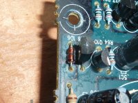
Some pictures:

I am having trouble identifying the diode labeled 1D6. It measures open in both directions. It leads from the input rectifier diode/RC timing circuit to the transistor bases. I gather they are back-to-back NPN/PNP pair. You can see the one that has exploded (Q106).
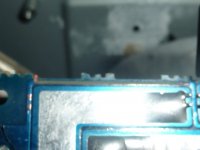
Here is the trace (top of board). I did not solder any parts connected to the trace so I doubt it was anything I did although that is still a possibility given my soldering skills . Trace is completely destroyed.

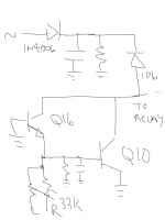
I'm working on a rough schematic. Thanks again for your help!

I am having trouble identifying the diode labeled 1D6. It measures open in both directions. It leads from the input rectifier diode/RC timing circuit to the transistor bases. I gather they are back-to-back NPN/PNP pair. You can see the one that has exploded (Q106).
Here is the trace (top of board). I did not solder any parts connected to the trace so I doubt it was anything I did although that is still a possibility given my soldering skills

I'm working on a rough schematic. Thanks again for your help!
That is my fear. Something drastic. The collectors go to ground and the emitters go via two resistors to the +ve outputs of each channel. There seems to be lots of things driving the bases including a line coming from the over-temp circuit. It doesn't look like they drive the relay itself.
I'm still determining how much need to be replaced or if the transistor itself (Q10 and not Q106 as previously stated ) was the culprit. Would such a small transistor be capable of pulling in such currents (must have been over an amp if the 1n4006 shorted and the trace lifted) if say the base shorted to ground?
I'm still determining how much need to be replaced or if the transistor itself (Q10 and not Q106 as previously stated
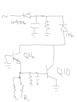
Ok. Yes, the rectifier was backwards. So here is the updated schem

If Q10 is an NPN, then considering that the diodes and Q10 appear to be the only affected parts, what could have been the cause of the failure? The amp has a rail voltage of 50V so the most current at the base of Q10 would be 1.5ma + whatever Q16 is providing.
Just to note that there is another driver circuit between this one and the relay.
Hard to say, you can analyse this sort of thing indefinitely.
I would say that for the transistor to explode like it did required another conductive path to what is shown via the components. No whisker of wire or solder blob anywhere?
As it's a simple circuit I would replace all in the area unless you find a definite cause.
What if Q10 was in partial conduction (large Vce drop and passing relay current). That would rapidly overheat it.
Could be important to see the rest of the relay driver as well...
As that failure happened right after your soldering activity, I can imagine the following
- ESD due to poor grounding of you and/or your soldering iron
- some kind of overvoltage, causing the diode and the transistor to fail
- metal where it should not be
As that failure happened right after your soldering activity, I can imagine the following
- ESD due to poor grounding of you and/or your soldering iron
- some kind of overvoltage, causing the diode and the transistor to fail
- metal where it should not be
Excellent point on the iron tatus.
Remember if the amp is grounded even via interconnects etc then a grounded iron is a "direct shorting link" as you touch it on components. It would present a dead short to a charged reservoir cap and pull currents through semiconductor junctions.
Remember if the amp is grounded even via interconnects etc then a grounded iron is a "direct shorting link" as you touch it on components. It would present a dead short to a charged reservoir cap and pull currents through semiconductor junctions.
- Status
- This old topic is closed. If you want to reopen this topic, contact a moderator using the "Report Post" button.
- Home
- Amplifiers
- Power Supplies
- Faulty supply problem
