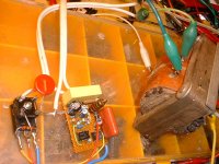
Here is a possible answer (the mad scientist version) to this problem:
What is the elegant way to convert 220? to 110V? - diyAudio
This circuit is basically a phase control system allowing the power to flow for 30° on either side of the zero crossing of the 230V input waveform (sin 30° = 0.5).
It uses a MOS rather than an SCR or triac to improve flexibility and to conduct twice per half-cycle.
Doing so has a number of advantages: it reduces the stress on the circuit elements and almost doubles the ripple frequency seen at the output of the transformer.
The conduction is a little larger than 30°, because the V.s product with this waveform is smaller and allows it, and because the leakage inductance of the transformer will cause a larger drop wrt. to the peak voltage than a regular sinusoid.
One screenshot shows the result with a simulated transformer, and the other on a pure resistive load.
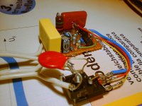
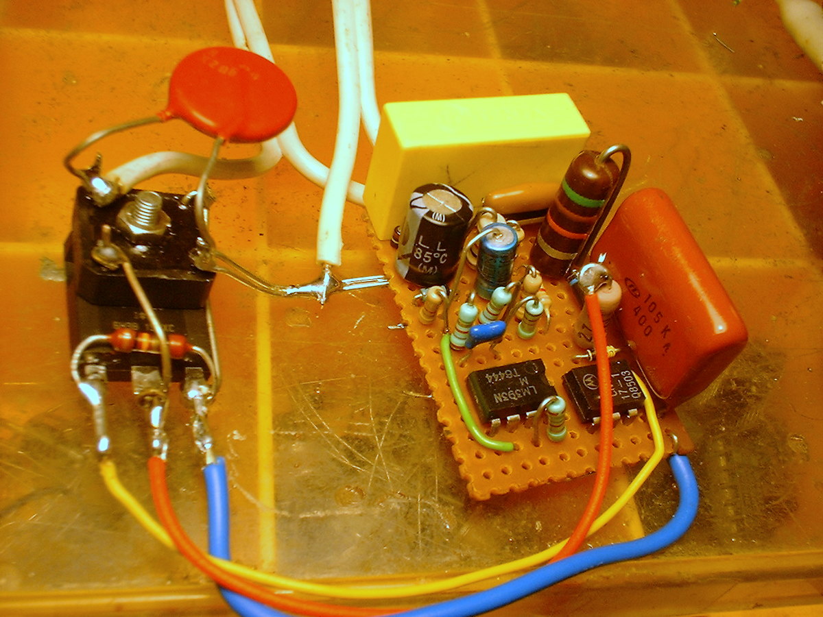
The IC can be a LM393. The ground connection is for simulation purposes only.
Note that the circuit also acts as a soft- start.
Disclaimer:
If you choose to build this circuit, it is your sole responsibilty, etc etc
What is the elegant way to convert 220? to 110V? - diyAudio
This circuit is basically a phase control system allowing the power to flow for 30° on either side of the zero crossing of the 230V input waveform (sin 30° = 0.5).
It uses a MOS rather than an SCR or triac to improve flexibility and to conduct twice per half-cycle.
Doing so has a number of advantages: it reduces the stress on the circuit elements and almost doubles the ripple frequency seen at the output of the transformer.
The conduction is a little larger than 30°, because the V.s product with this waveform is smaller and allows it, and because the leakage inductance of the transformer will cause a larger drop wrt. to the peak voltage than a regular sinusoid.
One screenshot shows the result with a simulated transformer, and the other on a pure resistive load.
The IC can be a LM393. The ground connection is for simulation purposes only.
Note that the circuit also acts as a soft- start.
Disclaimer:
If you choose to build this circuit, it is your sole responsibilty, etc etc
Attachments
I suspect phase control will not produce a very happy audio system. Think of having light dimmers nearby, and the trouble they create. Now feed your system off a light dimmer, and get ready for some real buzz.
Still think the easiest way is to stroll down to your local building supplies merchant and buy one of those fetching yellow step-down transformers they use for 110V power tools.
On ebay they frequently pop up for next to nothing s/h and they come in all conceivable sizes..
On ebay they frequently pop up for next to nothing s/h and they come in all conceivable sizes..
One more thing:
Thanks to the frequency-doubling effect, the peak voltage (and consequently the useful output power from the transformer) can be susbtantially increased:
The conduction angle can be increased to 60° without risk of causing the core material to saturate, leading to a peak primary voltage of 280V in a 230/115V system.
On the other hand, the ripple can be optimized by choosing a 45° angle, thus making 4*F the dominant ripple frequency, yielding 230V peak primary voltage.
The conduction angle can be modified by increasing the value of R9.
Still think the easiest way is to stroll down to your local building supplies merchant and buy one of those fetching yellow step-down transformers they use for 110V power tools.
If you are tempted to try it, be prepared for odds sounds. Those 240:110Vac site isolation transformers (in the UK) have massive leakage inductance designed-in - it's part of the fault current limiting strategy, and doesn't matter to 50Hz power tools. It's also mostly why they run so damn hot even when unloaded.
The following example compares the situation of a conventional 115V sinusoid solution with the voltage converter set at a higher conduction angle.
The average output voltage rises from 32V to 48V, a 50% increase, while the ripple voltage goes down by 1V pp (much more as a percentage).
Yet, the transformer's core utilization is still lower, meaning lower iron losses.
The average output voltage rises from 32V to 48V, a 50% increase, while the ripple voltage goes down by 1V pp (much more as a percentage).
Yet, the transformer's core utilization is still lower, meaning lower iron losses.
Attachments
If you are tempted to try it, be prepared for odds sounds. Those 240:110Vac site isolation transformers (in the UK) have massive leakage inductance designed-in - it's part of the fault current limiting strategy, and doesn't matter to 50Hz power tools. It's also mostly why they run so damn hot even when unloaded.
I haven't tried it personally but whenever I see american musicians here they almost invariably have the instruments amps plugged into those.
Friend of mine uses an US-made SWR bass amp which kept breaking down. He eventually had it back-converted to 110V and is using one of those now without problems. Similarly I know of a few people who bought US studio equipment using them. All without odd noises or problems.
In addition, the circuit also acts as a line voltage regulator: because the conduction time is decided by comparing the incoming waveform with a fixed reference, the output voltage has a constant peak value.
It is therefore a universal power supply front-end, accepting mains voltages from 100 to 300V~, depending on the MOS rating.
It is therefore a universal power supply front-end, accepting mains voltages from 100 to 300V~, depending on the MOS rating.
And in addition will act like a huge voltage-spike generator on the secondary side of the transformers that are fed with such a voltage shape (due to the switching on non-zero transitions).
I would not tie that output to an equipment that has any kind of transformer or even direct rectifier/switched power supply.
I would not tie that output to an equipment that has any kind of transformer or even direct rectifier/switched power supply.
And in addition will act like a huge voltage-spike generator on the secondary side of the transformers that are fed with such a voltage shape (due to the switching on non-zero transitions).
I would not tie that output to an equipment that has any kind of transformer or even direct rectifier/switched power supply.
Have you read the title?
Here is an elegant (insane?)
By the way, SMPS based supplies see even larger spikes, and 1,000 times more often too.


Do not use wave shaping circuit with transformer & electronics ....... too many HARMONICS are present ...........
Wave shaping is uasefull with resistors ... heaters..... lightbulb ........ ect not transformer .
Wave shaping is uasefull with resistors ... heaters..... lightbulb ........ ect not transformer .
Correct me if I'm wrong, but the only advantage compared to a SMPS is that your solution doesn't need a high frequency transformer.
Because in term of complexity, it's as complex as a SMPS.
As a disadvantage, it puts nasty current spikes into the supply and into the circuit that constitutes its load.
Because in term of complexity, it's as complex as a SMPS.
As a disadvantage, it puts nasty current spikes into the supply and into the circuit that constitutes its load.
Last edited:
When you want to use a 110V appliance on a 220V mains, you don't use a SMPS, do you?Correct me if I'm wrong, but the only advantage compared to a SMPS is that your solution doesn't need a high frequency transformer.
Do you really think this is as complex as a 1KW SMPS?Because in term of complexity, it's as complex as a SMPS.
As I said earlier, this has to be taken with a pinch of salt.As a disadvantage, it puts nasty current spikes into the supply and into the circuit that constitutes its load.
The title says:
Here is an elegant (insane?) ....
But even that remains open to the discussion.
What you see looks like a nasty waveform.
But what the rectifiers and reservoir capacitors see is a doubled frequency, with current spikes reduced in amplitude.
I am not sure you can tell a priori how an amplifier will behave, and in some cases, it might actually improve the situation compared to a regular 100Hz ripple
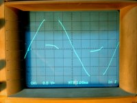
I've always known big hunks of iron (transformers) to be great circuit conditioners. So what does the output of a transformer fed by this circuit look like? I'll bet not bad at all.
Please show us!
Doc
Please show us!
Doc
The oscilloscope screenshot is exactly that.So what does the output of a transformer fed by this circuit look like? I'll bet not bad at all.
Please show us!
It is unloaded. With a rectifier and filter caps, the tops of the waveform are clipped
In a standard PSU, with bridge rectifier and reservoir capacitors in the secondary of a transformer, the conduction angle of each diode is less than 180 degrees of the sine cycle. So under load, the transformer will see current pulses anyway.
The circuit from post #1 seems to work as an forward converter for the first conductive cycle of the halfsine and as an flyback converter for the last.
The circuit from post #1 seems to work as an forward converter for the first conductive cycle of the halfsine and as an flyback converter for the last.
There is a small flyback episode, but the main operation is purely forward.The circuit from post #1 seems to work as an forward converter for the first conductive cycle of the halfsine and as an flyback converter for the last.
But when the primary is interrupted under load, there is a small parasitic flyback spike caused by the leakage inductance of the transformer.
This spike is handled by the gate supply of the MOS, which also serves as a snubber.
Additionally, the prototype also has a MOV across the MOS, not shown on the schematic
What about the little issue of the output voltage from your insano circuit being zero for most of the input cycle???
-Charlie
-Charlie
- Status
- Not open for further replies.
- Home
- Amplifiers
- Power Supplies
- Here is an elegant (insane?) way of converting 220V to 110V