This is the basic circuit of what was called the "magnetic filed amplifier." The Soundcraftsman version included a temperature sensor in the transformer to reduce the voltage even more if it began to heat up!
Most places with electrical codes banned it as it had horrible power factor.
The major difference is that in the amplifier the triac switched on at peak voltage so the transformer saw 120 HZ instead of 60. That allowed a smaller core and saved money.
I use a similar circuit after the transformer for power amplifiers. It allows a rail voltage that stays constant even with varying input AC and also allows a second higher voltage supply for the front end. All on one transformer.
I don't know of the magnetic field (I suppose that's the correct spelling) amplifier.The major difference is that in the amplifier the triac switched on at peak voltage so the transformer saw 120 HZ instead of 60. That allowed a smaller core and saved money.
But I don't see how, using "natural" switching in a triac, the frequency could be doubled.
In fact, that's precisely the reason why I opted for a MOS, as it allows for a complete freedom of the control (thus frequency doubling).
In theory, forced switching with a triac would be possible, but I have never seen it implemented anywhere, which is understandable given the peculiarities of triacs.
Anyway, this circuit has no ambition of improving amplifiers, just voltage halving with some side benefits.
BTW, I have also developed the complementary version (again, just for fun): an AC voltage doubler.
DC voltage doublers have been with us for a century or so, but so far there was no equivalent in AC (as simple I mean). That gap has now been bridged

I don't know of the magnetic field (I suppose that's the correct spelling) amplifier.
But I don't see how, using "natural" switching in a triac, the frequency could be doubled.
In fact, that's precisely the reason why I opted for a MOS, as it allows for a complete freedom of the control (thus frequency doubling).
In theory, forced switching with a triac would be possible, but I have never seen it implemented anywhere, which is understandable given the peculiarities of triacs.
Anyway, this circuit has no ambition of improving amplifiers, just voltage halving with some side benefits.
BTW, I have also developed the complementary version (again, just for fun): an AC voltage doubler.
DC voltage doublers have been with us for a century or so, but so far there was no equivalent in AC (as simple I mean). That gap has now been bridged
The triac is fired at the peak of the AC cycle, as the current is then available for 1/2 the time this has the same result as if the input frequency were doubled!
A linear (non-switching) version of this circuit (a BJT was used as a controled resistor) was used in some russian tape recorders to control the speed of induction machines. The motor was conected instead of the transformer.
BTW, Bob Carver has patented something like your circuit (not identical).
A magnetic amplifiers is a saturable inductor placed in series with a a.c. load. It was used in early color television sets to adjust picture size (EW correction).
BTW, Bob Carver has patented something like your circuit (not identical).
A magnetic amplifiers is a saturable inductor placed in series with a a.c. load. It was used in early color television sets to adjust picture size (EW correction).
A linear (non-switching) version of this circuit (a BJT was used as a controled resistor) was used in some russian tape recorders to control the speed of induction machines. The motor was conected instead of the transformer.
BTW, Bob Carver has patented something like your circuit (not identical).
A magnetic amplifiers is a saturable inductor placed in series with a a.c. load. It was used in early color television sets to adjust picture size (EW correction).
We call a saturable inductor used to control current a "Reactor." A real magnetic amplifier uses a reactor and an HF supply.
Bob Carver did patent something. I am pretty sure Paul Rolfes (SP?) at Soundcraftsman (The guys who were first with graphic equalizers!) did it first and did not patent anything as he had seen it used in other power control applications.
But what the rectifiers and reservoir capacitors see is a doubled frequency, with current spikes reduced in amplitude.
Actually with a small leakage transformer the current spikes are increased, since conduction angle is reduced, and average current must be the same. In case of high leakage inductance the current spikes may not increased, but all energy in leakage inductance is wasted as heat. In both case the overall loss is much higher than in normal operation.
Analysis must include current and power. It would show strong drawbacks.
The only way this can work well (with not increased loss): small leakage (eg. toroidal transformator) + inductor after rectifier. But it won't be stable (I mean load independent) in any case, without control loop.
Trying without load: doing nothing, proves nothing.
If you care to read the whole thread, you'll see that these issues have been adressed:Actually with a small leakage transformer the current spikes are increased, since conduction angle is reduced, and average current must be the same. In case of high leakage inductance the current spikes may not increased, but all energy in leakage inductance is wasted as heat. In both case the overall loss is much higher than in normal operation.
Analysis must include current and power. It would show strong drawbacks.
The only way this can work well (with not increased loss): small leakage (eg. toroidal transformator) + inductor after rectifier. But it won't be stable (I mean load independent) in any case, without control loop.
Trying without load: doing nothing, proves nothing.
The notion of conduction angle is misleading: it is true that the raw conduction angle (the MOS conduction time) is less than 360° for a period, but in fact this says nothing about the actual conduction angle, imposed by the rectifier and the filter cap.
This angle will always be much less than 360°.
In a conventional bridge + capacitor configuration, the average output current to the load is transported through two current pulses/cycle. The actual angle and pulse height will depend on the specifics of the circuit, capacitor, transformer, etc.
If the same average current is transported with 4 pulses/cycle, everything else remaining equal, the height of each pulse will be ~halved.
The actual factor will be somewhat different, again depending on the circuit specifics, and for optimum operation the 4 pulses should be spaced equally, which won't be the case because this would impose an output voltage which will not be the target, but there will be some gain.
Regarding the energy stored in the leakage inductance, the problem has been acknowledged, and the wasted energy is partially recycled in the gate drive supply. Depending on the actual configuration, it might be prohibitive, but this also depends on the circuit's specifics.
Since there are some gains (lower transformer induction for example), it can be advantageous -or not-, but the main purposes of this circuit are:
a) to have some fun (I don't advise building it, and I haven't actually used it)
b) to change a transformer's voltage without adding too much impedance or losses
If you care to read the whole thread, you'll see that these issues have been adressed:
I did, but no real answer.
The notion of conduction angle is misleading: it is true that the raw conduction angle (the MOS conduction time) is less than 360° for a period, but in fact this says nothing about the actual conduction angle, imposed by the rectifier and the filter cap.
Actually I analised the real conduction angle on secondary. It can be done based on output voltage waveform. ic=du/dt.
This angle will always be much less than 360°.
In a conventional bridge + capacitor configuration, the average output current to the load is transported through two current pulses/cycle. The actual angle and pulse height will depend on the specifics of the circuit, capacitor, transformer, etc.
If the same average current is transported with 4 pulses/cycle,
Which are much-much shorter. The sum is still shorter than 2 normal pulses. It can be seen on your waveforms.
everything else remaining equal, the height of each pulse will be ~halved.
Absolutely not. You haven't even tried to determine current if you believe this. Do your homework! Don't just count the number of pulses, measure duration also, or even better to measure current directly! You will find that current is increased (with the values you provided). (With higher inductance current is decreased, but in the expense of a very high loss...)
The actual factor will be somewhat different, again depending on the circuit specifics, and for optimum operation the 4 pulses should be spaced equally, which won't be the case because this would impose an output voltage which will not be the target, but there will be some gain.
Regarding the energy stored in the leakage inductance, the problem has been acknowledged, and the wasted energy is partially recycled in the gate drive supply.
But it will not return to the load, where it should be. Gate drive power requirement should have been insignificant.
Depending on the actual configuration, it might be prohibitive, but this also depends on the circuit's specifics
Since there are some gains (lower transformer induction for example), it can be advantageous -or not-, but the main purposes of this circuit are:
a) to have some fun (I don't advise building it, and I haven't actually used it)
It was obvious for me that you haven't used it. But not for those of who you suggested to build. And you did advise it (this because I found it):
http://www.diyaudio.com/forums/powe...ary-reduce-secondary-voltage.html#post4510934
b) to change a transformer's voltage without adding too much impedance or losses
It depends on what you call "too much". Is 100 % too much? Maybe not for somebody.
OK, it changes voltage, but this is all. No other good thing can be mentioned.
Well, you won't buy it, that's clear enough.
It is obvious that such an active circuit will generate additional losses compared to a purely passive, ideal and lossless voltage bucker: conduction losses, flyback losses, additional I²R losses for some configurations, control power, switching losses, etc.
But the contribution of each individual loss will be rather modest, and the total will never come close to 100%, that's a gross exaggeration (or deliberate sabotage).
This method has to be taken with a pinch of salt, I made that clear from the start, but I am convinced there are cases where it could be advantageous, when you take the full picture into account: losses are not everything, and if they can be kept at a reasonable level, the other advantages make it attractive: it is relatively simple, cheap, flexible (the transformation ratio can be easily adjusted), it reduces the ripple voltage, it provides a crude open-loop compensation of the input variations and it subjects the transformer's core to a smaller induction than an equivalent passive bucker for the same voltage.
Crappy efficiency
I estimated wrong. It's not 100 %. But 145...160 %. I made your homework:


Probably you are right, it will never be as low as 100 %. OK, at half load maybe
But it could have been 10% if L was placed between graetz and capacitor. With a bigger L and feedback from output a nearly perfect solution could have been made.
You sabotaged yourself when didn't want to measure any relevant things. Such as load regulation, efficiency, switching loss, EMC, real transformator parameters...
OK, at least these ones are true. However triac is simpler and cheaper.
OK, maybe, but with such a very bad load regulation you can use it only at constant load. Like heating and incandescent lamp. But they work easily without any transformer, only needs traditional phase splitter.
OK, so you achieve 0.5 W smaller histeresis loss.
Well, you won't buy it, that's clear enough.
It is obvious that such an active circuit will generate additional losses compared to a purely passive, ideal and lossless voltage bucker: conduction losses, flyback losses, additional I²R losses for some configurations, control power, switching losses, etc.
But the contribution of each individual loss will be rather modest, and the total will never come close to 100%, that's a gross exaggeration (or deliberate sabotage).
I estimated wrong. It's not 100 %. But 145...160 %. I made your homework:
Probably you are right, it will never be as low as 100 %. OK, at half load maybe
But it could have been 10% if L was placed between graetz and capacitor. With a bigger L and feedback from output a nearly perfect solution could have been made.
You sabotaged yourself when didn't want to measure any relevant things. Such as load regulation, efficiency, switching loss, EMC, real transformator parameters...
This method has to be taken with a pinch of salt, I made that clear from the start, but I am convinced there are cases where it could be advantageous, when you take the full picture into account: losses are not everything, and if they can be kept at a reasonable level, the other advantages make it attractive: it is relatively simple, cheap, flexible (the transformation ratio can be easily adjusted), it reduces the ripple voltage,
OK, at least these ones are true. However triac is simpler and cheaper.
it provides a crude open-loop compensation of the input variations
OK, maybe, but with such a very bad load regulation you can use it only at constant load. Like heating and incandescent lamp. But they work easily without any transformer, only needs traditional phase splitter.
and it subjects the transformer's core to a smaller induction than an equivalent passive bucker for the same voltage.
OK, so you achieve 0.5 W smaller histeresis loss.
Last edited:
Answering is probably a waste of time, since you hate the concept so much, and won't relent until you have utterly and completely crushed and annihilated it, but I will make single and final attempt, and let the forum members judge for themselves.
First a clarification: when I talk about efficiency, I mean the ratio of useful output power to the input power, and I acknowledged that there would be increased losses compared to an ideal, passive solution:
I am also perfectly aware that moving the circuit (or at least the power part) to the secondary of the transformer would eliminate the flyback losses issue, but the current topic is about a general-purpose voltage changer, a black-box placed in front of an equipment without any other connection or modification.
The sim you carried out is punitive (unsurprisingly), and results in higher losses than in my circuit. One of the main reasons is probably the way the snubber is connected in your sim.
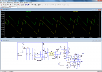
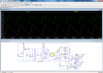
I will compare the power efficiency for the two situations: an ideal voltage step-down device against the complete dropper circuit.
In most respects, it will be more realistic and even harsher than your own sim, because it includes all of the losses, including the conduction losses of the MOS and diodes, the control power, the auxiliary snubber, etc. Nothing will be left out.
I will also post the simulation file, to allow others to try for themselves and challenge it.
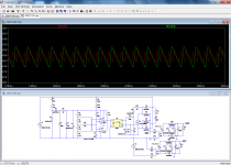
The first pic shows both output voltages: V2 has been adjusted to exactly equalize them.
The second pic shows the resulting output power: 226.16W.
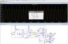
The third pic shows the average output power supplied by the reference source: 245.3W. The efficiency is thus 92.2% for this case.
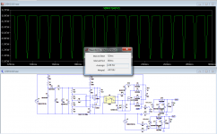
Fourth pic shows the power supplied to the voltage changer: 266.21W, efficiency 84.9%, a degradation of 7.3 points.
Is it excessive? It depends on the context and one's appreciation. For something that would be operated 24h/7d at the maximum power, it certainly is.
For a power amp that will draw a very small average power with an occasional peak, it is probably acceptable, and is certainly preferable than using dropping impedances or ballasts.
...Which doesn't mean that a PA will accept such a harsh waveform, but that is another debate (the title of the thread says it all).
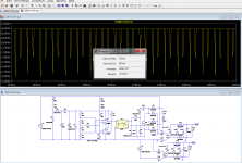
What about the load regulation? The fifth pic shows the situation at half-load: there is a moderate degradation compared to the reference, but not what you would call catastrophic.
What about the line regulation? Sixth pic shows the situation for a 10% drop of the input voltage. Unsurprisingly, the reference does clearly worse than the voltage changer, which in fact overcompensates slightly.
Thus, is it all dark, bad and hopeless? I let everyone form his own opinion and I also post the .asc file.
It is also worth noting that the comparison has been made with an ideal step-down device, and an actual transformer would in reality not be perfect either.
First a clarification: when I talk about efficiency, I mean the ratio of useful output power to the input power, and I acknowledged that there would be increased losses compared to an ideal, passive solution:
b) to change a transformer's voltage without adding too much impedance or losses
I am also perfectly aware that moving the circuit (or at least the power part) to the secondary of the transformer would eliminate the flyback losses issue, but the current topic is about a general-purpose voltage changer, a black-box placed in front of an equipment without any other connection or modification.
The sim you carried out is punitive (unsurprisingly), and results in higher losses than in my circuit. One of the main reasons is probably the way the snubber is connected in your sim.
I will compare the power efficiency for the two situations: an ideal voltage step-down device against the complete dropper circuit.
In most respects, it will be more realistic and even harsher than your own sim, because it includes all of the losses, including the conduction losses of the MOS and diodes, the control power, the auxiliary snubber, etc. Nothing will be left out.
I will also post the simulation file, to allow others to try for themselves and challenge it.
The first pic shows both output voltages: V2 has been adjusted to exactly equalize them.
The second pic shows the resulting output power: 226.16W.
The third pic shows the average output power supplied by the reference source: 245.3W. The efficiency is thus 92.2% for this case.
Fourth pic shows the power supplied to the voltage changer: 266.21W, efficiency 84.9%, a degradation of 7.3 points.
Is it excessive? It depends on the context and one's appreciation. For something that would be operated 24h/7d at the maximum power, it certainly is.
For a power amp that will draw a very small average power with an occasional peak, it is probably acceptable, and is certainly preferable than using dropping impedances or ballasts.
...Which doesn't mean that a PA will accept such a harsh waveform, but that is another debate (the title of the thread says it all).
What about the load regulation? The fifth pic shows the situation at half-load: there is a moderate degradation compared to the reference, but not what you would call catastrophic.
What about the line regulation? Sixth pic shows the situation for a 10% drop of the input voltage. Unsurprisingly, the reference does clearly worse than the voltage changer, which in fact overcompensates slightly.
Thus, is it all dark, bad and hopeless? I let everyone form his own opinion and I also post the .asc file.
It is also worth noting that the comparison has been made with an ideal step-down device, and an actual transformer would in reality not be perfect either.
Attachments
- Status
- This old topic is closed. If you want to reopen this topic, contact a moderator using the "Report Post" button.
- Home
- Amplifiers
- Power Supplies
- Here is an elegant (insane?) way of converting 220V to 110V