When I came up with the Kmultiplier I didn't imagine one would try to use it on a tube amp or something with really high rails. This makes it necessary to change some things. Anyone who doesn't want to consult with me on a Kmultiplier for over 50V use should use this schematic - with an input lytic of course.
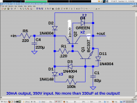
How much voltage drop is acceptable? This version should work for up to 350V, and have more PSRR owing to the input RC.
http://www.diyaudio.com/forums/powe...ntokens-cfp-cap-multiplier-5.html#post3281140
Post 236
If you don't like the input RC, I have some other versions that will work but are not tested.
So, you need a bulky version. 100mA at 90V is 10W! So it seems you're running the drivers off the frontend rails.
You definitely need C5171/A1930 outputs, and an input RC is not acceptable. If your frontend capacitance is not humongous, as I've had to account for in the past, then a 3rd transistor may not be necessary.
You definitely need C5171/A1930 outputs, and an input RC is not acceptable. If your frontend capacitance is not humongous, as I've had to account for in the past, then a 3rd transistor may not be necessary.
I have built a K-multiplier for use as a pre-buffer for a Salas CCS/shunt regulator.
The output CCS is designed for 1 amp and it works fine.
I still saw some diode bumps (less than half a mV) on the output so I decided I needed a pre-reg. I inserted the K-multiplier on the negative rail.
Inserting the CFP multiplier, the current drops to 100 milliamps.
- I also see the voltage across the multiplier is arbitrarily 6-7 volts (depends if I use the CCS or a resistor). I did omit the LED by the way.
- Is this an area (high voltage) where I should not use this circuit? [I remember having read something like that]
- Is it true that there is a current limiting inherent in the circuit? What is the use then of a CCS?
Last edited:
I have loaded the circuit with a 100 ohms resistor; input 14 V.
I installed the LED (I had omitted it because my cap is just 10 uF)
When I turn the power on, the LED lights, and dims somewhat but not totally.
I guess I got it: I use a TIP29C [Hfe <75] /a NPN HF transistor [about 100]; the combo is not very strong then. It is struggling to get current.
will have to look for a better combo in my box of available components then
I cannot guess what voltages and currents you are trying to run it at. If you look at the webpage in my signature you'll see that the max current for the C5171/A1930 version is 500mA or so. It may work up to 2A but probably not as well.
Here is a version designed for high voltage:
http://www.diyaudio.com/forums/powe...ntokens-cfp-cap-multiplier-5.html#post3281140
What is the CCS current? How much capacitance at the output of the multiplier?
Here is a version designed for high voltage:
http://www.diyaudio.com/forums/powe...ntokens-cfp-cap-multiplier-5.html#post3281140
What is the CCS current? How much capacitance at the output of the multiplier?
The purpose is for a shunt running at 0,8 to 1 amp. That is a lot for the DFP I understand. It is for 5 Volts out; input is 11-12 volts and raw input RMS is less than a volt; the CCS/Salas are there to take it to 5 volt.I cannot guess what voltages and currents you are trying to run it at. If you look at the webpage in my signature you'll see that the max current for the C5171/A1930 version is 500mA or so. It may work up to 2A but probably not as well.
What is the CCS current? How much capacitance at the output of the multiplier?
The intermediate capacitances are not great; but I tested at 10.000 uF.
Why was the salas not enough?
In the Salas shunt output I saw residual glitches on my scope of less than a mV, but they were visible in the noise as a fast rising edge; this prompted me to add a capacity multiplier.
A normal one (with darlington) on the positive line worked well and reduced it to almost invisible;
so I decided to test the Kmultiplier; to see if that was better - and I put this kmultiplier on the earth line.
My analysis:
Very probably I got the problem because of using non-stock parts: I used diodes salvaged from boards; and these have a higher conduction point of almost 0,7 V; and I used TIP29C/BFX37. The BFX is exotic, I agree (but I have them) and looking at the specs it is a low level low noise transistor and I should replace it. The TIP has an Hfe of about 60; too low too probably (but it can cope with the 1A current for sure).
I'll test the base (diode) current.
albert
I thought you were using it at tube voltages! It is very important to use a BC3x7 or BC5xx for the driver, as this is what get you high isolation. The C5171/A1930 are somewhat critical too.
I would think that visible ripple at the output of the Salas reg would indicate the circuit is broken somehow. Oscillation triggered by rectifier bursts? BUT, I have not studied the Salas reg in some time.
If you get it to work with other transistors, that will be great, although you probably won't get 60db isolation. Ripple at the driver base and driver emitter should be the same. Vbe of the driver should be no more than 700mV or so. It sounds like your slave transistor is not doing it's job, and so the driver is overworked and pulling down the reference voltage.
The purpose is for a shunt running at 0,8 to 1 amp. That is a lot for the DFP I understand. It is for 5 Volts out; input is 11-12 volts and raw input RMS is less than a volt; the CCS/Salas are there to take it to 5 volt.
The intermediate capacitances are not great; but I tested at 10.000 uF.
Why was the salas not enough?
In the Salas shunt output I saw residual glitches on my scope of less than a mV, but they were visible in the noise as a fast rising edge; this prompted me to add a capacity multiplier.
A normal one (with darlington) on the positive line worked well and reduced it to almost invisible;
so I decided to test the Kmultiplier; to see if that was better - and I put this kmultiplier on the earth line.
albert
Hi Albert
Does the probe end bit have a short to GND path? If it has the usual 15cm earth cable with the crock it can pick up stuff. Due to very low impedance of PSU seeing 1Meg of a scope, the test loop becomes an antenna. Use the short springy pointy bit that comes with the probes or just wrap a naked wire around the nose's earth sleeve after pulling off the hook's cone. Allow it a straight end up to the tip. Evaluate again then.
If EMI from hard switching at 1A passes nonetheless, a small value power resistor between bridge and main filter is usually effective for reducing at source. 1 Ohm 3-5W.
EMI is high frequency enough for the CCS to be no better than a ballast resistor anymore. So some pre-filter simple or active is not a bad idea.
Thanks Salas, yes the usual RF artifacts from the test jig!
You must be right - but I must admit I saw some improvements anyway.
I don't have a real probe. My "probe" point has a 14 cm unshielded tip. Just a BNC to banana plug to a probe point. And the earth line is connected separately at the scope via a separate wire.
- Room for improvement then!
I can't take good artifact pictures right now (camera in repair) but I can show the sets [with slight artifacts] and the improvement [on the artifacts]. But I will try to use mobile phone (blurred and out of focus I think).
I will try the resistor; 1 ohm, before the supply cap; and also 5 ohm in mains line. I use a pretty good Schaffner transformer with just 53 pF between mains and secondaries. I use a BYV32 'ultrafast' rectifier.
albert
Using the Kmultiplier before a shunt regulator is a great idea since there is no inrush. Used this way the Kmultiplier could be used at very high voltages without concern for inrush or overvoltage.
Before a CCS it overcomes the instability sometimes seen with inductive ["BAD"] resistors; I used 0,68 ww just to see it triggered on the inrush; with a stabilised prereg. in my test set, it was OK. The Kmultiplier provides a very stable environment.
- With a standard cap-multiplier you can change the base current by varying the base resistor. This then makes a kind of CCS. Output 100 Hz can be as low as 5 mV at 1 amp in my rig (-45 dB already with the TIP122 darlington).
- do I need to improve on that?
Keantoken,
In the K-multiplier the current is set by R2 and the diodes if I understand correctly; varying R8 just might provide a CCS function . . .
- Home
- Amplifiers
- Power Supplies
- Keantoken's CFP cap multiplier