the second filament of all the broken H4 auto headlamp bulbs you did not throw out.No need for anything exotic here; just scratch around the house for something that has about 50 ohms DC resistance - maybe an electric toaster or some lightbulbs wired up in parallel or .... ?
Member
Joined 2009
Paid Member
If you look at the F5 and your PSU, do you find that the speaker currents flow through the last set of capacitors in the power supply ? It's often the case that they do. In which case, a virtual earth for the F5 is perhaps the same thing as a single rail supply plus an output capacitor on the amplifier ?
Just resurrecting this thread because I'm fascinated by the power supply arrangement Quad have used here! Apologies if this is just conventional stuff to many people, but judging by this thread, this PSU configuration has passed some people by (like me).
http://www.diyaudio.com/forums/powe...und-power-amp-applications-3.html#post2326158
Why have Quad used this method? Looking at it, I think it might be because it confers the following advantages:
1. The transformer secondary doesn't need a centre tap.
2. Only one fuse in the transformer secondary side means that if it blows, the ground stays symmetrically between the supply rails as the power collapses. From the earlier 405 schematics and its conventional split supply, I can see that Quad had thought long and hard about the positions of the two fuses, in relation to the input and output stages' power.
3. Although the amp output is not capacitor coupled (it behaves exactly like a DC coupled amp output), if one of the output devices goes short, or partially short, there is no DC path via the speaker to +ve or -ve (well, only a high impedance), so only the energy held in (one of) the PSU caps can be discharged through the speaker even if the fuse doesn't blow, thus limiting damage.
It only works for AC applications (not a problem for audio, obviously), but apart from that, are there any disadvantages to this PSU arrangement?
Here's a VERY INTERESTING virtual ground circuit I worked out recently, (with some help from people at head-fi.org), which should also lend well to chip amp applications, although the TO-220 regulators are going to need heat sinks, for sure. It offers positive and negative outputs with 1.5 amps of current from each, simultaneously at up to about +/- 37V. see the whole article either here:
http://www.diyaudio.com/forums/solid-state/234665-virtual-ground-regulated-rail-splitter.html
or here:
A Regulated Virtual Ground Circuit
or here:
Vitual Ground (regulated!) - and Rail Splitter Circuits!
http://www.diyaudio.com/forums/solid-state/234665-virtual-ground-regulated-rail-splitter.html
or here:
A Regulated Virtual Ground Circuit
or here:
Vitual Ground (regulated!) - and Rail Splitter Circuits!
An externally hosted image should be here but it was not working when we last tested it.
Last edited:
WOW! This looks like just what I need. I do have a couple questions - not really a newbee (I've been building/modifying kits for ~50 years, but some of this is still new to me):Hi Andrew
The circuit below could be good. The opamp is used as a unity-gain buffer. R3 and R4 simply limit it's loop gain for stability.
R5 is included to ensure that the bulk of the current flows through the caps, so the opamp will only have to deal with the relatively small DC offset current (and some low frequency ripple).
R5 should also help with opamp stability, and is low enough to ensure minimal DC offset voltage.
Regards - Godfrey
1- What controls the V+/V- voltage? Or is it always 1/2 the input?
I will be using a tranny with ~72VAC secondary so ~90 VDC post rectification. Currently I have a MOSFET regulator resulting in a stable 70VDC. My plan would be to add this virtual ground circuit to create +/- 35VDC to power two LM3886 amps. Do you see any problem with this?
2- This shows my lack of knowledge of the LM3886. I can follow all the connections in your schematic, but is it fine to just leave the mute pin (#8) unconnected? Also what about pin #7 which typically goes to ground?
Thanks for the help.
I think using another 3886 for this job is massive overkill. A somewhat beefed up version of the Quad could easily do the job.WOW! This looks like just what I need. I do have a couple questions - not really a newbee (I've been building/modifying kits for ~50 years, but some of this is still new to me):
1- What controls the V+/V- voltage? Or is it always 1/2 the input?
I will be using a tranny with ~72VAC secondary so ~90 VDC post rectification. Currently I have a MOSFET regulator resulting in a stable 70VDC. My plan would be to add this virtual ground circuit to create +/- 35VDC to power two LM3886 amps. Do you see any problem with this?
2- This shows my lack of knowledge of the LM3886. I can follow all the connections in your schematic, but is it fine to just leave the mute pin (#8) unconnected? Also what about pin #7 which typically goes to ground?
Thanks for the help.
Another option would be to put the amplifying 3886's themselves to task, and generate their own VG, without any supplementary circuit.
If you post your exact schematic, we can see how to tweak it to accomplish this
Hex Buffer, MOSFETs Build A High-Power, Lossless, Virtual Ground | Power content from Electronic Design
Is this any good for audio?
Is this any good for audio?
")
In my limited experience with a virtual ground, it works very VERY well.
I have not tested the one in AndrewTs link, I have my own circuit for it - which I can not make public unfortunately, since I am going to sell it to a high end audio company to Germany.
Anyhow, what I like in the virtual ground approach is the fact of the matter that it makes the both rails to sag equally and therefore forces the 0V line rock solidly between the two rails - allways.
My virtual ground is made with generic opamp and class B mosfet (cfp) output stage...
Sorry for the delay. I was away from internet for a bit. Here is the schematic for the amps, pretty straight forward chipamp. As I said, PS at this point is regulated 72V and I need to split it to +/-36V.I think using another 3886 for this job is massive overkill. A somewhat beefed up version of the Quad could easily do the job.
Another option would be to put the amplifying 3886's themselves to task, and generate their own VG, without any supplementary circuit.
If you post your exact schematic, we can see how to tweak it to accomplish this
I have extra LM3886 chips, so that is not a problem, but I am always interested in more 'elegant' solutions.
Thanks for the input.
Attachments
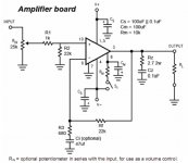
You can use a circuit like this one: the components designators are the same as in your schematic where it applies.
C5 and Ci are not critical, they should just be large enough and preferably bipolar since they will see the offset voltage of the amplifier which could be either direction.
C4 is optional.
The virtual ground potential is enforced via the load. If you want to have a predictable behavior when no load is connected, you can add another resistive splitter in parallel with the 4700µ capacitors
Attachments
I think I understand the circuit, but what is its advantage over the 3886 based PS? I have a bunch of the 3886 kicking around so that actually appeals more (even if overkill) unless I am missing something that makes this circuit better.You can use a circuit like this one: the components designators are the same as in your schematic where it applies.
Thanks
It spares one 3886, but of course if you have bucket loads of them,....I think I understand the circuit, but what is its advantage over the 3886 based PS?
The schematic has omitted the DC blocking capacitor on the input.Sorry for the delay. I was away from internet for a bit. Here is the schematic for the amps, pretty straight forward chipamp. As I said, PS at this point is regulated 72V and I need to split it to +/-36V.
I have extra LM3886 chips, so that is not a problem, but I am always interested in more 'elegant' solutions.
Thanks for the input.
It has also omitted the RF filter on the input.
- Status
- This old topic is closed. If you want to reopen this topic, contact a moderator using the "Report Post" button.
- Home
- Amplifiers
- Power Supplies
- Virtual ground in power amp applications