Fair point...
But for me, the objective is what I learn more than anything else. So given I understand how to generate a virtual ground via the voltage divider setup of the resistors, and I've never setup a virtual ground with a op-amp/active circuit, I'll probably give that a try.
And to be honest, I keep looking at that voltage divider arrangement, and intuitively I don't understand why that voltage divider is what defines the ground point between the rails, and not the varying resistance over both sides of the load (ie the amp)?
Perhaps I'll set it up in such a way that I can try it with and without the active virtual ground and see what happens....
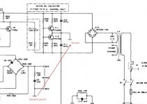
Quad 606 floating ground
...I found the schematic for the Quad 606 (I have no idea about the details of that amp...) floating ground setup. Can anyone give me a bit of insight as to the relative merits of the approach we've been discussing and this circuit?
...I found the schematic for the Quad 606 (I have no idea about the details of that amp...) floating ground setup. Can anyone give me a bit of insight as to the relative merits of the approach we've been discussing and this circuit?
Attachments
Safety Earth & Virtual Ground
The chassis, if conductive, MUST be connected to Safety Earth (Protective Earth).
If the speaker ground in Quad's 606 schematic has an exposed conductive part then Speaker Ground MUST also be connected to chassis.
Similarly, if the input socket has an exposed conductive part, it too MUST be connected to Chassis.
This is why I asked in post13, "do you need to? "
I apologize if i'm slow on the uptake...
By "do you need to" do you mean do you need to connect the virtual ground to the chassis ground (and hence to the earth on the mains plug)? or do I misunderstand?
To clarify by what I meant as safe grounding earlier, it pretty much just echo's what you just said. If you can touch it, and it conducts, then it should be connected to earth. Yes, absolutely. Is your point that you don't need to attach the virtual ground to the chassis ground (and hence earth), and that there's some sort of advantage to wiring the thing up this way?
Last edited:
Unfortunately the absolute maximum supply voltage for both LT1970 and LT1210 is 36V (+-18V), so neither can be used here.
agreed, I had misread the initial post as 24v, not +/-24v. they can be placed back to back for higher current, but voltage is a nogo. pity that its an excellent and quite novel chip that keeps part count to a minimum.
what you can do though is use it as a straight up opamp driving 0v from the center of a divider buffered by a mosfet or paralleled if higher current is needed
Last edited:

if the audio terminals & connectors are not composed of exposed conductive parts then I believe the regulations allow the Virtual Ground to be isolated from the Chassis.By "do you need to" do you mean do you need to connect the virtual ground to the chassis ground (and hence to the earth on the mains plug)? or do I misunderstand?
To clarify by what I meant as safe grounding earlier, it pretty much just echo's what you just said. If you can touch it, and it conducts, then it should be connected to earth. Yes, absolutely. Is your point that you don't need to attach the virtual ground to the chassis ground (and hence earth), and that there's some sort of advantage to wiring the thing up this way?
However,
what happens at the other end of the cables that are connected to this amplifier?
For the Safety of other users, visitors, children, I would always connect these insulated parts to the Chassis by way of a Disconnecting Network.
The advantage of the Virtual Ground is that all 3 poles of the dual polarity supply are isolated from the chassis. This leaves open the designer's choice of which to connect to Chassis, It does not have to be the Virtual Ground that gets the connection. You may obtain better performance by using one of the +/- voltage poles to the chassis.
It's an active circuit as Andrew said, but a really limp-wristed one, with performance even worse than the simple passive circuit shown earlier.what do you think of the quad schematic? I'm curious to get feedback on efficacy as it'll be cheaper to do, vs the use of a LM3886?
The goal of any of these virtual ground circuits is to keep the DC voltage on the virtual ground as close as possible to half way between the positive and negative supply voltages, even if there is some DC offset current.
Two weaknesses of the Quad circuit are:
A) It allows the voltage to drift about +-0.7V from where it should be before the active devices (the transistors) even turn on.
B) The transistors are current-limited to about 25mA. If the DC offset current is larger than that, the voltage error will quickly get large.
Below is a comparison of roughly how much voltage error to expect on the virtual ground for each of the three circuits, for different amounts of DC current:
Active circuit (post 8):
1mA DC => 1mV error
10mA DC => 10mV error
20mA DC => 20mV error
40mA DC => 40mV error
Passive circuit (post 3):
1mA DC => 50mV error
10mA DC => 500mV error
20mA DC => 1V error
40mA DC => 2V error
Quad 606:
1mA DC => 700mV error
10mA DC => 1V error
20mA DC => 1.3V error
40mA DC => 23V error !!!
The Quad circuit is still quite rational, though.
If the DC offset current is less than about 25mA (which seems to be their assumption), then the voltage on the virtual ground will be within about 1.5V of where it should be.
Points in favor of the Quad circuit are that it's fairly simple and inexpensive, and it should run cool without wasting much power.
If required, it could always be improved at the expense of some added complexity.
e.g. In the version below:
A) The diodes (and R5 and R6) have been added to give the transistors some forward bias to get rid of the +-0.7V "dead zone".
B) R3 and R4 have been reduced to increase the current handling to about 100mA.
Hmm, this is almost identical to one of the circuits you linked to in post 6, except that one didn't have current limiting resistors.
Attachments
that's looking like a good solution
Cheers for that analysis of the voltage error in the various circuits - very helpful!
I reckon I'll give your solution a shot then. It seems to have the benefits of accuracy with a reasonable part count, and I've most of those bits on hand anyway (with the exception of those transistors).
Again, thanks for the help; I'll try and keep this thread updated with my progress as I go and whether the end result works out well.
Actually, I do have a pile of small signal transistors - BC557, 559, 558, 549, 547, 548. Could I use these (or several of them in parallel?) in this circuit? I'm about to read all of their datasheets to get some understanding as to their suitability, but it's all new to me so i'd certainly be happy to hear any advice!
Nothing special about those - BD139 and BD140 just came to mind first as I've known them "since I were a lad", which isn't much of a recommendation. There's bound to be better modern parts that I'm not familiar with.(with the exception of those transistors)
The ZTX ones used by Quad are better in terms of gain, but can't dissipate as much power.
To get some ideas, you could look at other solid-state designs and see what they're using for VAS or drivers.
According to these lists, the following look like likely candidates:
2SC3421 and 2SA1358
2SC2911 and 2SA1209
2SD669 D/AC/C and 2SB649 D/AC/C
2SC4793 and 2SA1837
I had a look at the datasheets - they all look OK, but might appreciate heatsinks.
Edit: oops, I missed a few posts there while I was scratching around.
Those small-signal transistors might be OK, if you use 2 or 3 in parallel instead of one bigger transistor BUT make sure their voltage rating is high enough. According to some datasheets I found:
BC546, BC547, BC550=good
BC548, BC549 =bad
BC556, BC557, BC560=good
BC558, BC559 =bad
If you do that, each transistor must have it's own emitter resistor though.
Last edited:
OK, so I was running around getting a quote on some transformers for a F5 amp build, and I came across a transfo (625VA, 38-0, 38-0 secondaries) which was for sale for a song... so I bought it figuring it'd be good for a class AB build. The I got to thinking (always dangerous!) about my f5 build and started wondering about whether I could use the transfo I have somehow...
So the F5 wants rails of +/- 24V and with 38V secondaries I'd end up with an unloaded rail voltages of around +/- 53V.... which is almost double what I actually need... So I started wondering about voltage doubling rectification, and so arrived at the following questions.
Is there a way to (exactly) halve the voltage output after rectification?
Any suggestions?
Hello,
This is not half but is much closer. Consider a choke input power supply following your transformer. Check out this Hammond pdf http://www.hammondmfg.com/pdf/5c007.pdf . A little CRCR filtering and you are there.
DT
Hi Godfrey,
Cheers for the answer - just as a check of the concept, I might try the BC5?? transistors first. Should I be happy about the end result, I'll give the appropriate single chip solution the go. I know DIY audio always tends to the extreme's (because we can), but I always tend to find myself at the 'bang for the buck' end of the performance curve, so I'll probably go with the BD transistors seeing as I've used them before quite happily.
Cheers for the emmittor resistor comment - I wouldn't have realized myself")
Cheers for the answer - just as a check of the concept, I might try the BC5?? transistors first. Should I be happy about the end result, I'll give the appropriate single chip solution the go. I know DIY audio always tends to the extreme's (because we can), but I always tend to find myself at the 'bang for the buck' end of the performance curve, so I'll probably go with the BD transistors seeing as I've used them before quite happily.
Cheers for the emmittor resistor comment - I wouldn't have realized myself
Well, I got myself all the requisite parts to go ahead and build this powersupply, so off we go. I'll try and build something over the weekend, but as it stands I have no amp to provide a load to test the end unit. Any suggestions as to how I can test what I build with a highly asymmetric, variable load to see how it goes? ...Actually, is this the right way to test it anyway? In lieu of an amp and a set of ears what is the best way to test performance here?
Hmm, Dunno, good question.
I suppose a good start would be to just hook up a load between the positive and negative rails to draw an amp or so of current and see what happens.
No need for anything exotic here; just scratch around the house for something that has about 50 ohms DC resistance - maybe an electric toaster or some lightbulbs wired up in parallel or .... ?
- Status
- This old topic is closed. If you want to reopen this topic, contact a moderator using the "Report Post" button.
- Home
- Amplifiers
- Power Supplies
- Virtual ground in power amp applications