Please forgive if this is a dumb question, but this gizmo is just to avoid toroid hum? Are there any other ill effects -to the transformer/s) due to "normal" amount of DC present in the mains supply?
I´m finishing my current project which is a dual mono 300WRMS/channel with 650VA toroids, and agree they hum at different levels, mostly depending on time across the day, humming the least at night, which is consistent with everything expressed previously regarding neighbours electric loads and so on.
Being the DC blocker a dangerous circuit by nature (may become explosive upon time as electros age), my question is if it is really worth or not???
I must say I raised the output stage bias to 250mA and idle hum got greatly reduced.
"Being the DC blocker a dangerous circuit by nature (may become explosive upon time as electros age), my question is if it is really worth or not??? "
Bryston offers a 20 year warranty with their product, and meets UL, CSA, and most other agency approvals. Crown also meets the same agency approvals, but does not use the caps.
Bryston offers a 20 year warranty with their product, and meets UL, CSA, and most other agency approvals. Crown also meets the same agency approvals, but does not use the caps.

Last edited:
Well, 20 years is a decent timeframe. Guess that will depend on the electrolytics quality.
Just a follow up and to avoid sounding all out dumb -in case I'm able to achieve this :- I refer above to tranformer hum, not ground related hum. I'm not a transformer specialist but guess hum level will diminish if primary current goes up slightly. At least that happened to both toroids in my project.
I must say I raised the output stage bias to 250mA and idle hum got greatly reduced.
Just a follow up and to avoid sounding all out dumb -in case I'm able to achieve this :- I refer above to tranformer hum, not ground related hum. I'm not a transformer specialist but guess hum level will diminish if primary current goes up slightly. At least that happened to both toroids in my project.
How do you measure that?Have you checked the range of VDC while it's been in-circuit (by hooking DMM across it)?
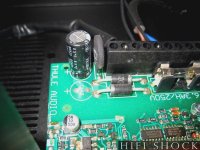
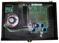
in the attached images you will find the components of Anders Thule's DC filter solution (in the AC mains line) from the first circuit by post #1 (pdf attachment). In the IA150B image the mains AC input board is licated behind the toroidal transformer
The second capacitor isn't in use in most cases (C48 in the first picture) and the voltage of the other (used) cap at this place is only 6,3 volts.
By Thule amps there are many other shortcommings in case of the realibility, but until this day I haven't observe an exploded or defectice capacitor at this place. For me this is really amazing - but nevertheless I want this not to justify.
Attachments
Last edited:
Rod Elliot's DC blocker is NOT "a dangerous circuit by nature." The caps aren't really doing much in normal operation (except during switch on inrush). The ESP article explains this...Being the DC blocker a dangerous circuit by nature (may become explosive upon time as electros age), my question is if it is really worth or not???
I must say I raised the output stage bias to 250mA and idle hum got greatly reduced.
Mains DC and Transformers
My experience is the opposite of yours and is what lead me to assemble my own DC blocker: As I turned up the bias, my ~250VA transformer got louder in general. And with the cover off, it made more noises...
About not using any caps, Rod Elliot says:Crown also meets the same agency approvals, but does not use the caps.
"Additional tests I performed used only diodes (no effect whatsoever), and a 22uF and 1uF capacitor, and both of these were completely useless. Actually, they were worse than useless, by actually creating a DC offset!"
Rod Elliot's DC blocker is NOT "a dangerous circuit by nature."
The caps aren't really doing much in normal operation (except during switch on inrush). The ESP article explains this...
Mains DC and Transformers
AFAIU the circuit, I can not agree with you on the above statement.
The capacitors are actually doing the whole job, specially under no load or light loads until the event in which the current value through them raises enough so that the diodes will take over, preventing capacitors from overloading.
My experience is the opposite of yours and is what lead me to assemble my own DC blocker: As I turned up the bias, my ~250VA transformer got louder in general. And with the cover off, it made more noises...
My experience is in accordance with the concept below, extracted from the ESP article. If you draw current from the traffo secondary, will cause core saturation to lower, hence mechanical hum should lower as well.
As I understand, if your toroid/s increase growl along with current then a DC blocker might not be a solution to your problem.
I might be wrong so I gladly accept feedback.
.....Most of the time, the DC offset is transient - it appears for a short while, then goes away again. When it is there, toroidal transformers may complain loudly, by making growling or buzzing noises. It is important to understand just how this happens, and what can be done about it if it causes problems.....
.... With larger transformers (500VA and above), the DC resistance is usually so low that even a very small offset will cause mechanical noise due to saturation.....
.....From the DC perspective, the most critical region is at no-load. The saturation effects are greatly reduced when we are drawing significant current, so we will hopefully be able to simplify the circuit......
I'm not on top of all the noises that the Chinese ~250VA trafo in my Adcom makes. The DC blocker is keeping the torriod as quiet as ever (no dynamic noises), but it is still too buzzy, so it must be mechanical from being wound sloppy. I think a soft mount of some kind will be best...
AFAIU the circuit, I can not agree with you on the above statement.
The capacitors are actually doing the whole job, especially under no load or light loads until the event in which the current value through them raises enough so that the diodes will take over, preventing capacitors from overloading.
.... With larger transformers (500VA and above), the DC resistance is usually so low that even a very small offset will cause mechanical noise due to saturation.....
.....From the DC perspective, the most critical region is at no-load. The saturation effects are greatly reduced when we are drawing significant current, so we will hopefully be able to simplify the circuit......[/COLOR]
Yes, the diodes are the protectors for the electrolytics against voltages above 700mV.
A question: what are online concerning reports and papers to this topic in your language (Spanish language)? Thank you for advices.
Yes, the diodes are the protectors for the electrolytics against voltages above 700mV.
A question: what are online concerning reports and papers to this topic in your language (Spanish language)? Thank you for advices.
No articles in spanish regarding this topic that I'm aware of.
I admit I prefer english spoken forums as they bring together a wider spectrum of knowleadge.
Which other suppliers there are with such dc blocker devices on PCB like
L C Audio Technology / DC Filter
and
http://www.psaudio.com/ps/products/detail/humbuster-iii ??
more threads to basic discussions:
NAP 200 Humming | Naim Audio Forums
http://www.diyaudio.com/forums/solid-state/37942-diy-ps-audio-humbuster.html
????? ???????? ??????? PS Audio Humbuster III » hifisound.com.ua
ronronnement de transformateur torique - Page 5 sur le forum Amplification du site Homecinema-fr.com - 29803367 - 1056
Are there interesting news concerning commercial available DC blockers against buzzing toroidal transformer cores ?
Hum Curred
Thanks for all the pointers. I have been putting up with a lot of transformer hum. I built the circuit referenced in this site. It is in my power distribution box serving 2 large OTL tube amps and a music server.
Mains DC and Transformers
I used 2 big electrolytic caps.. 30v 12,000 uf. They have 8A ripple current.
The initial results were terrible. Much more humming from all the torroids. It sounded like they were being overloaded. I felt it possible they were starving for sufficient current. I added 2 more caps. MUCH better but still some hum.
Added 2 more caps. Now 3 pairs of series caps with a total of 72mf. All hum from all transformers gone. The biggest change was much improved dynamics and sound quality. Clearly ridding the transformer saturation was a good thing for the sound.
Attachments
mlloyd1
I cannot be certain... given the first set had a negative effect, the second set improved the hum over the starting point and the 3rd set completely eliminated it, I would say it was required and successful. There are a lot of big transformers being fed. One other key was that after the first set, a 10A isolation transformer would present no hum, but by switching on amps and adding a fair bit of load it would hum like crazy. After the second set of caps it would strain for 2-3 seconds then settle down to a dull hum. With third set, all stable.. no hum, better dynamics. The amps each have 2 torrids for high load filament supply to 6c33c tubes plus a large pair of torroids for driving the power tube b+.
I put this post out there in case anyone follows the path and finds this approach degrades the situation with heavier load. You may just need to work out the math and add more ripple current capacity.
hmmmmm,
(no pun intended)
that sounds like an awful lot of capacitance for this application.
are you sure it was powerline DC-caused toroid hum you were trying to eliminate?
mlloyd1
Yes, I am confused as well. I would think that as long as the reactance of the capacitor is less than, say. 0.25 ohms at 60Hz, that should be enough. That would be 10,100uF if my calculation is right. Using an NP cap would be nice, but I'm not sure they easily come that big. Low ESR is important, but high voltage rating is less important given that the diodes are there and we rarely want the drop across the capacitors to get up to 0.7V anyway. If the voltage across the cap is limited to less than 1 volt, does anyone know if we can get away with a polarized cap without a reliability or other problem? Anyone tried?
Cheers,
Bob
does that equate to 72mF or something else?total of 72mf.
6 caps in series parallel coming to 72mF, requires each capacitor to be 12mF.
Is that what you used?
The capacitance of six series/parallel connected 12mF is 18mF
The impedance of these 6 caps in series parallel is predicted to be
Xc=1 / {2PiFC} = 1/{2*3.14*50*0.018} = 0.18ohms for a 50Hz supply.
The peak voltage across the diodes must not exceed ~400mVpk for each diode not to pass and for the DC blocker to remain effective.
The maximum peak current across the capacitors will therefore be ~0.8Vpk/0.18ohms ~ 4.5Apk
That is the peak voltage of the primary current pulses that must not be exceeded for the DC blocker to work.
For the Canadian mains frequency the allowable peak current is 6/5ths of that figure, i.e. 5.4Apk for 60Hz.
you are right and you could, with a little bit of arithmetic, have modeled the effect.mlloyd1
I cannot be certain... given the first set had a negative effect, the second set improved the hum over the starting point and the 3rd set completely eliminated it, I would say it was required and successful.
Mlloyd1 is wrong. He does not understand.
BTW, I use 3m3F 16Vdc polarised caps. 10 in series parallel works effectively for my 50Hz 240Vac supply.
I suspect that both 6Vdc and 10Vdc would be equally effective. But the diodes must protect the caps even during a fault condition through the blocker. I have used 1n5404, but not tested it for fault current.
Last edited:
The Bryston 4BSST uses two 33,000uF, 6.3V polarized capacitors connected in parallel in opposing directions across the blocking diodes. They use a high-current bridge rectifier to implement the blocking diodes.
Most of the time the capacitors will be conducting high-current spikes of relatively low duty cycle, as is normal for rectifier circuits, as opposed to sinusoidal current.
Inrush current at turn-on may be stressful to these circuits, so it might be a good idea to employ a soft-start circuit.
Cheers,
Bob
- Home
- Amplifiers
- Power Supplies
- Variations of DC Main Filter against buzzing Toroid Transformers - what is the right?