Resistor (22 Ohm) is necessary to select from limits of 10-100 Ohms . Power of resistor will withstand short-time maximum voltage on capacity (see below), in the set mode power in resistor repeatedly decreases.
.
Without this resistor the capacitor charge occurs quickly, for one half-cycle or power line ~220 Volts. But the recharge of capacitor is caused not only the initial mains voltage ~220 Volts, but also depend under the influence of power loading. In case of power loading saltus that is characteristic for POWER AMPLIFIER, there will be also a voltage surge on capacitor. And it means that part of energy will be taken from customers at the time of origin of a saltus of power loading. That is, if on pulse the capacitor is recharged on 2 Volts, these 2 Volts will be subtracted from 310 Volts in the first half-cycle. That will pull for itself the transition process in inductivity of magnetization of a toroide.
.
With the resistor power will be selected more softly, within several periods of frequency of power line ~220 Volts with constant time of RC, but some very little time voltage on capacitor to come into an opposite polarity.
.
Without this resistor the capacitor charge occurs quickly, for one half-cycle or power line ~220 Volts. But the recharge of capacitor is caused not only the initial mains voltage ~220 Volts, but also depend under the influence of power loading. In case of power loading saltus that is characteristic for POWER AMPLIFIER, there will be also a voltage surge on capacitor. And it means that part of energy will be taken from customers at the time of origin of a saltus of power loading. That is, if on pulse the capacitor is recharged on 2 Volts, these 2 Volts will be subtracted from 310 Volts in the first half-cycle. That will pull for itself the transition process in inductivity of magnetization of a toroide.
.
With the resistor power will be selected more softly, within several periods of frequency of power line ~220 Volts with constant time of RC, but some very little time voltage on capacitor to come into an opposite polarity.
Last edited:
You are looking at the wrong operational case.
Look instead at the "passing FAULT current" situation just before the fuse blows !!!!*!!!!
That schematic is dangerous and you obviously do not know how it should operate.
It should be removed from this Forum.
Before you are responsible for killing someone !!!!*!!!!
Look instead at the "passing FAULT current" situation just before the fuse blows !!!!*!!!!
That schematic is dangerous and you obviously do not know how it should operate.
It should be removed from this Forum.
Before you are responsible for killing someone !!!!*!!!!
Isol-8 MiniSub Axis
robert | follis | associates | photos
.
This device is used the same circuit as our circuit.
Differently between circuits is that our circuit is used two capacitors, ISOL 8 is used many capacitors connected to parallel forming two capacitors.
.
robert | follis | associates | photos
.
This device is used the same circuit as our circuit.
Differently between circuits is that our circuit is used two capacitors, ISOL 8 is used many capacitors connected to parallel forming two capacitors.
.
AndrewT
.
http://www.vegalab.ru/forum/showthr...евом-фильтре?p=1186196&viewfull=1#post1186196
.
See here, but all in Russian.
This is description of calculation parameters to this circuit.
.
.
http://www.vegalab.ru/forum/showthr...евом-фильтре?p=1186196&viewfull=1#post1186196
.
See here, but all in Russian.
This is description of calculation parameters to this circuit.
.
AndrewT
.
??????? - ???????
.
See here, but all in Russian.
This is description of calculation parameters to this circuit.
.
This could be the ultimate approach. In order to assess this surely, I need the AC inrush (and follow the idle) current flow through each part during the start-up phase. This all at different torodials with different performance and power classes so as different ratio between core wight and copper wight.
Unfortunately the losses by language translating are too large.
Last edited:
AGREE! And this ESP/ Rod Elliot DC blocker really could not be any simpler to build: 2 caps and a diode bridge. (I built the 120V version, and it works.)Far simpler to follow the ESP circuit which is based on the various (correct) posts on this Forum.
tiefbassuebetr: While I do appreciate that you are trying to be helpful and thorough, what is the point of forever collecting and diagramming every possible half-baked variation on this DC-blocking theme, even while AndrewT points out that some are potentially unsafe?
The reason therefore is to find the most reliable and safe approach. AndrewT points out, that some of the variants are potentially unsafe, unfortunately without exact explanations and good to understand substantiation.AGREE! And this ESP/ Rod Elliot DC blocker really could not be any simpler to build: 2 caps and a diode bridge. (I built the 120V version, and it works.)
tiefbassuebetr: While I do appreciate that you are trying to be helpful and thorough, what is the point of forever collecting and diagramming every possible half-baked variation on this DC-blocking theme, even while AndrewT points out that some are potentially unsafe?
Please note: even if all agree, all can be wrong.
My own prever solution is currently the approach from BMW850 - go to post number seven about
http://www.htforum.nl/yabbse/index.php?topic=86686.0
(same as circuit from first file of post 80 here)
because there is no possibility of an unwanted reverse polarized voltage at the electrolytics. In order to a higher current flow I prefer a 63V version instead the showed 16V version.
Last edited:
Guys:
None of these circuits is intrinsically safe, as long:
- Capacitors are rated below 400VDC
- Polar electrolytes are used
- Faulty open or shorted diodes are able to turn the circuit into an "explosion machine"
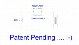
For moderate powers I would personally suggest:
1x 2200uF/700V MKP (For energy electronics) and 100Ohms/400W in parallel (to the cap), mounted on a sufficient heatsink ...
None of these circuits is intrinsically safe, as long:
- Capacitors are rated below 400VDC
- Polar electrolytes are used
- Faulty open or shorted diodes are able to turn the circuit into an "explosion machine"
For moderate powers I would personally suggest:
1x 2200uF/700V MKP (For energy electronics) and 100Ohms/400W in parallel (to the cap), mounted on a sufficient heatsink ...
Last edited:
Exuse me,
What scheme you are mean ?
.
I expected, that this question would come ...
I mean the most "simple" circuit possible: A single coupling capacitor, snubbered by a resistor (To dampen resonance).
Attachments
bypass facilities for a non polar MKP (foil) capacitor?Jon, from your comments and diagram it appears you don't understand how a DC blocker works in the supply to the transformer.
Your diagram will only work for small currents.
It has no bypass facility for transient currents during switch on or similar.
By this rated voltage? Why? And which parts you mean?
ckeck out this URLs:
WIMA MKP6
http://www.conrad.de/medias/global/ce/4000_4999/4500/4520/4524/452418_BB_00_FB.EPS_1000.jpg
WIMA DC-LINK MKP 6 Zwischenkreis-Kondensatoren
Hi all
I just built a DC blocker and as I am a (dangerous) noob when it comes to electronic I figured I'd better have the experts look it up before I power it up and burn the whole house
It is a simple pair of capacitors (+ terminals connected together) paralleled with a bridge rectifier (+/- terminals connected together).
It is the same circuit as the one presented by Rod Elliott in the conclusion fo his "Mains DC and Transformers" article
I am using BHC 100,000uF 40V capacitors, and a KBPC5010 bridge (50A)
(yes I got a little bit overboard...).
Are those values correct? Any ill effect when combining these values I would have overlooked?
I plan to use this with a powerful amplifier (MC2 MC1250).
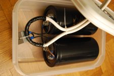
Attached is a photo of the circuit in a temporary box (but as things are going it might well be there for a long time...).
Obviously it is hard to see much with this photo, but everything is correctly connected, following Rod Elliot's circuit.
What do you guys think?
I just built a DC blocker and as I am a (dangerous) noob when it comes to electronic I figured I'd better have the experts look it up before I power it up and burn the whole house
It is a simple pair of capacitors (+ terminals connected together) paralleled with a bridge rectifier (+/- terminals connected together).
It is the same circuit as the one presented by Rod Elliott in the conclusion fo his "Mains DC and Transformers" article
I am using BHC 100,000uF 40V capacitors, and a KBPC5010 bridge (50A)
(yes I got a little bit overboard...).
Are those values correct? Any ill effect when combining these values I would have overlooked?
I plan to use this with a powerful amplifier (MC2 MC1250).
Attached is a photo of the circuit in a temporary box (but as things are going it might well be there for a long time...).
Obviously it is hard to see much with this photo, but everything is correctly connected, following Rod Elliot's circuit.
What do you guys think?
Attachments
Last edited:
pos, seems fine, component-wise. Not easy for me to double check your wiring by the pic, but you say it's correctly connected.
But if it were in my house I would want to have it in a grounded metal box, in case something gets hot -- or worse -- i.e. the same precautions as with anything plugged in to an electrical outlet.
But if it were in my house I would want to have it in a grounded metal box, in case something gets hot -- or worse -- i.e. the same precautions as with anything plugged in to an electrical outlet.
common, this is a box meant for microwave cooking, it should take the heat
Thank you for your answer, I will try to find a metal box of appropriate size (damn me, why did I choose those big capacitors...). What component could get hot?
I will at least try the circuit in this box, as soon as my amp starts to hum again (it is desperately quiet since I build the circuit, go figure...)
Last edited:
SOP (standard operating procedure) for when **** happens not due to your mistake. Pretty much any component, connector, solder joint, etc. on its way out can get hot due to internal resistance...
Have you checked the range of VDC while it's been in-circuit (by hooking DMM across it)? I found in our house it's typically +20 to +30mV, but goes regularly to +70mV (and when our printer comes on it goes crazy +2V, -0.6V...)
Have you checked the range of VDC while it's been in-circuit (by hooking DMM across it)? I found in our house it's typically +20 to +30mV, but goes regularly to +70mV (and when our printer comes on it goes crazy +2V, -0.6V...)
- Home
- Amplifiers
- Power Supplies
- Variations of DC Main Filter against buzzing Toroid Transformers - what is the right?