After long journey I reached the goal to serch for Zobel of Reflektor +3.3V.
The story is following.(Of course no oscillation on all cases)...
Cheers
 for giving the subjective feedback.
Attachments

The Zobel damps the resonance/ringing if a fast transient unsettles the quiescent operation.
The resistor in the Zobel is what "damps" the resonance.
The capacitor is there to prevent the resistor burning out, due to excessive dissipation.
What you should have done was to experiment with changing the resistor value, while monitoring the rail during impulse activation. Once the resistor value is found you can then make the capacitor smaller until it begins to interfere with the damping, then go back up a value or two.
Kaz,
you mucked about with the capacitor until your hearing told you something was changed. Not at all what is required to optimally damp a resonant system.
4) 0R47+0.44uF(0.22u//0.22u)
Become great deep sound, no more harsh.")
I also guess that it is very good for 1R0+0.47u as Salas recommends.
On this experiment I found a few principles about Zobel.
1 Zobel is strongly related to quality of sound.
2 If Zobel is not been optimized, sound become harsh or dim.
3 The optimal value is between the narrower area than I expected.
Next step, I build Reflektor +1.2V. If I get good result, will report.
Best regard
On the simulator your choice looks well damped and extended for OLG. I could not get exact STP model, still with an alike but less for gfs and more for Crss Fairchild the output impedance for DVCC 1R5 R1 is 2.4mOhm flat for double the audio band and it only climbs to 3mOhm lazily at 80kHz. 1R+0.47u shows the same for Zo, bit better phase theoretically, but not sure without exact model, near prediction to yours indeed. Bottom line is, very good technically for no extra error amp stage and no buffer stage, a mirror does all that, very elegant.
1.2V will challenge the threshold...
Hey you know SAPPORO Beer! I love it.
Used to drink it where I could see it, pure taste, best can ever, could not squash, Rowland amps look like that beer can.
Sapporo Beer Commercial - Legendary Biru - YouTube
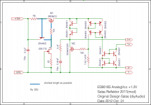
Reflektor +1.2V
Yes, there are two big walls of threshold, namely, Vgs and Vbe.
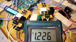
I have already built prototype, and running well with constant resistor load.
PS
SAPPORO BEER and Rowland amps.. woom, very impressed.
1.2V will challenge the threshold...
Yes, there are two big walls of threshold, namely, Vgs and Vbe.
I have already built prototype, and running well with constant resistor load.
PS
SAPPORO BEER and Rowland amps.. woom, very impressed.
Reflektor +1.2V
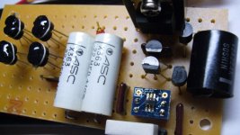
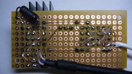
With joy I would like to announce that Reflektor +1.2V has come out.
Two big walls of threshold are overcome. Though I have no confidence to call this circuit pure Reflektor.
Last night I replaced old MOSFET source follower regulator, that is simple no-NFB type, with new Reflektor in my Sabre DAC. The sound has changed dramatically far beyond my expectations. Quoting Michael Elliott's words, "this one left us with dropped jaws". It is my impression.
Zobel is same as Reflerktor +3.3V, I have no need to change.
Attachments
Interesting stuff Kazuo! Thank you for sharing your adapted design! It’s very interesting and helpful to be able to make 5V and below Reflektors. I am going to try the version with STP55NF06L for a 5.25V supply (Buffalo 3 DAC).
Sabre DACS can sound fantastic with the right power supplies. The sound is really as good as power supplies go. With this DAC you (even) get rewarded for every subtle change you make in your power supply.
Peter
Sabre DACS can sound fantastic with the right power supplies. The sound is really as good as power supplies go. With this DAC you (even) get rewarded for every subtle change you make in your power supply.
Peter
The idea behind the Reflektor (correct me if I am wrong) is to reflect the current change in the reference leg (with the LED), in the regulator leg (where the FET is) in order to counteract a change in output voltage. So the mechanism relies on current change in the reference leg. This current change is greater when the dynamic impedance (dV/dI) in this leg is lower. That is the main reason I suppose why the LED is there. Since Vgs of the IRF640 is approximately between 4 and 4.5V, wouldn’t it improve the regulation of the FET when for exaple two red LEDS in series were used (together approx. 3.2V and well below 4V) instead of one green LED? That would lower the dynamic impedance in that leg (you need less series resistance) and thus cause more current change, which could improve the regulation. Is it a good idea to boost current change anyway or am I missing important design considerations?
Peter
Peter
For that purpose OK but to generally sink it, plus the dioded 4401s dissipation roof, small current stuff. How hot is it now for how much current you spare through it?
I was worried about same points before making.
In my case constant current is set on 115mA, and the current of target board is 10mA. MOSFET is running without heat sink. Touching finger, temperature of 4401s and MOSFET is a little bit warm.If more current is needed, they must be changed to another one which is more power dissipation.
Sabre DACS can sound fantastic with the right power supplies. The sound is really as good as power supplies go. With this DAC you (even) get rewarded for every subtle change you make in your power supply.
Peter
Thanks pietjaers.
I have same opinion with you. Sabre DAC is strongly affected by quality of power supply.
Good luck.
Hi all, I want to supply the input, VAS and pre-driver stages of a class A amplifier with + and - 37V using a Version 1 regulator. The DC voltage I have after rectafacation and filtering is + and - 51V. How do I calculate the value of R1 if I require 250mA ( or any other current ). Also at a later stage I may use this supply for the drivers where more current is needed if so would it be OK to select R1 for this higher current even if initially I do not require it? I appreciate that the shunt transistor will dissapate more heat .
Thanks for your help
Alan
Thanks for your help
Alan
your +-51Vdc is likely to rise to ~+-53Vdc worst case mains voltage.
This combined with 100mA for the CCS will dissipate a worst case 5.3W in each CCS mosFET if the output gets shorted.
Decide whether you want the mosFET to survive this worst case scenario. Then select the heatsink appropriately. If you go for this "survivability" and the heatsink is isolated from the chassis, then the FET can be bolted/clamped direct to the sink for lowest Rth c-s.
Vr1+VgsQ1 = Vledstring.
Arithmetic/algebra allows you to re-arrange the equation (or equality) to:
Vr1 = Vledstring - VgsQ1.
Vr1 also equals the current through the resistor times the resistance of R1, i.e.
Vr1 = R1 * Ir1
and re-arranged to give
R1 = Vr1 / Ir1
Put that back into our earlier re-arrangement and we get
R1 = [Vledstring - VgsQ1] / Ir1
You need Vledstring and VgsQ1 and Ir1
Let's assume, until you can measure your circuit, values for these knowns
Vledstring ~ 5.7Vdc
Ir1 = CCS current = 100mAdc = 0.1Adc
Vgs ~ 4Vdc
Put these into our equation and we get
R1 = [5.7 - 4.0] / 0.1 = 1.7 / 0.1 = 17r nearest e24 value is 18r.
Adopt 18r, or 20r, or 22r, or 24r, or 27r, or 30r, or 33r, or 36r.
That now allows you to directly measure that guessed at voltage of 1.7V across the R1 resistor.
Once you have that voltage you can calculate the actual CCS current.
If it's not big enough, then ADD second resistor that gives the extra current you want to give a total CCS current ~ =100mA.
Again lets suppose you measure 1.71Vdc across a 24r resistor in position R1.
CCS current = 1.72Vdc / 24r = 0.0716666 repeating ~ = 72mAdc.
You need an extra ~28mAdc (=0.026Adc).
1.72Vdc / 0.028 ~ 61r4.
Adopt 62r (nearest e24 value).
add this in parallel to the R1 already installed.
Remeasure Vr1. calculate the new CCS current. Is it close enough to your target?
Before closing let's check dissipation in R1.
Pq = V^2 / R = 1.72*1.72 / 24 = 0.123W
Use a 500mW or 600mW resistor.
If you had adopted a 18r and your Vr1 were found to be 1.95Vdc then Pq = 1.95^2 / 18 = 211mW. a 500mW resistor just about works but will run hot, too hot to hold with a finger pressed on.
that's the nice thing about using resistors in parallel. Each resistor runs considerably cooler than a single. eg two 36r in parallel for an effective 18r will dissipate 1.95^2 / 36 = 106mW. A 500mW resistor is OK.
Last edited:
- Status
- This old topic is closed. If you want to reopen this topic, contact a moderator using the "Report Post" button.
- Home
- Amplifiers
- Power Supplies
- The simplistic Salas low voltage shunt regulator